
Passenger seating arrangement

a seating arrangement and passenger technology, applied in the field of passenger seating, can solve the problem of consuming a large amount of space in the aircraft cabin of prior art sleeper-type seats

Active Publication Date: 2007-10-25
BE AEROSPACE INCORPORATED
View PDF25 Cites 96 Cited by
  • Summary
  • Abstract
  • Description
  • Claims
  • Application Information

AI Technical Summary

Benefits of technology

[0005]This need is addressed by the present invention, which provides an arrangement of sleeper seat units disposed in an angled configuration to allow for efficient telescoped placement thereof in an aircraft cabin.
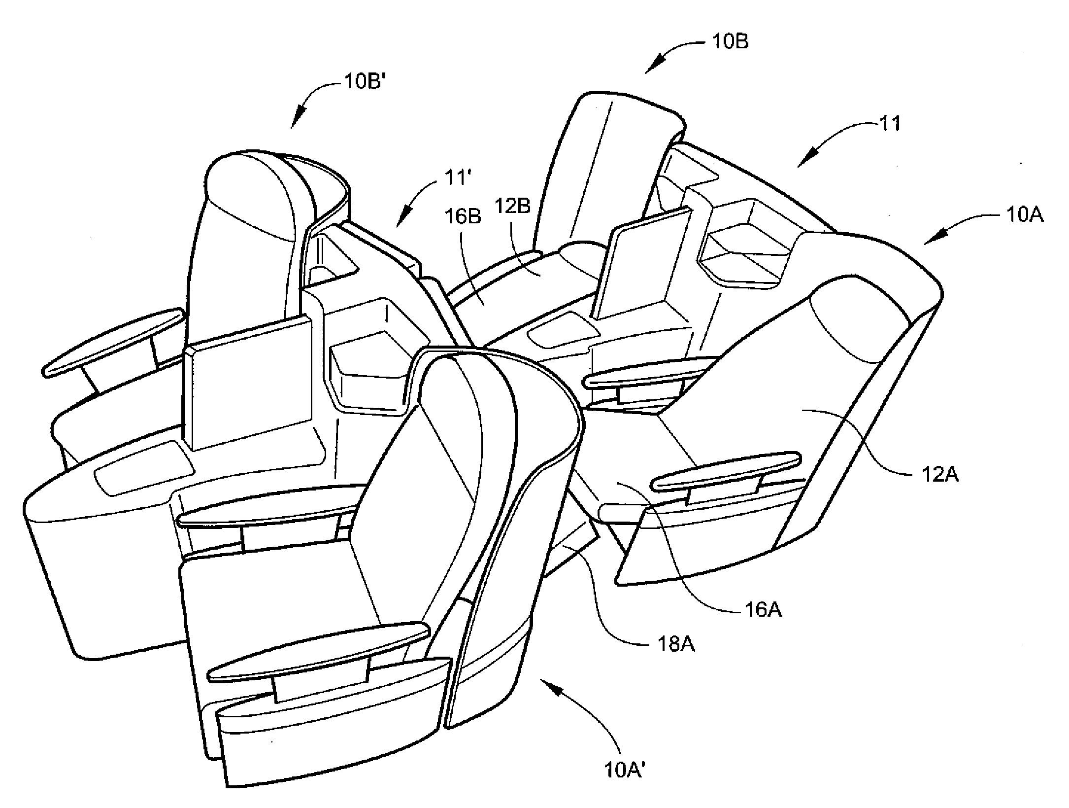
[0016]According to another aspect, the present invention provides aircraft seating for minimizing space occupied within an aircraft and being configurable to provide sleeping surfaces. The aircraft seating includes a first aircraft seat and a second aircraft seat that are each disposed at an angle with respect to a first longitudinal axis. Each of the aircraft seats includes a seat back, a seat bottom, a leg rest, and spaced-apart arm rests. A center unit is positioned between the aircraft seats. A recess is formed in the center unit for receiving the feet of passengers sitting behind the first and second aircraft seats. The foot well has support surfaces defined therein.

Problems solved by technology

While such seats provide good passenger comfort, there are deficiencies in this arrangement.
Prior art sleeper-type seats consume a large amount of space within the aircraft cabin.

Method used


Image

  • Passenger seating arrangement
  • Passenger seating arrangement
  • Passenger seating arrangement

Examples


Embodiment Construction

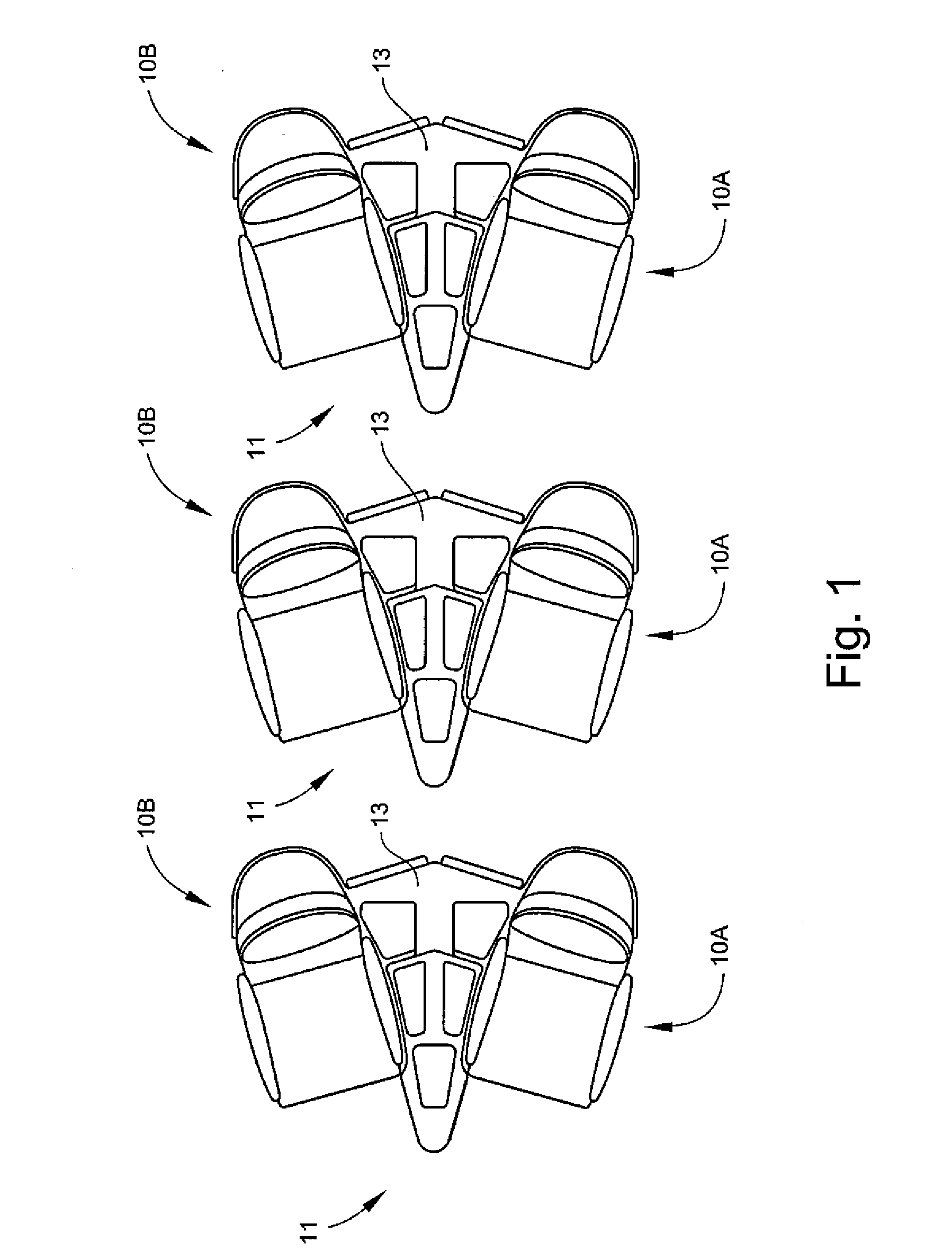
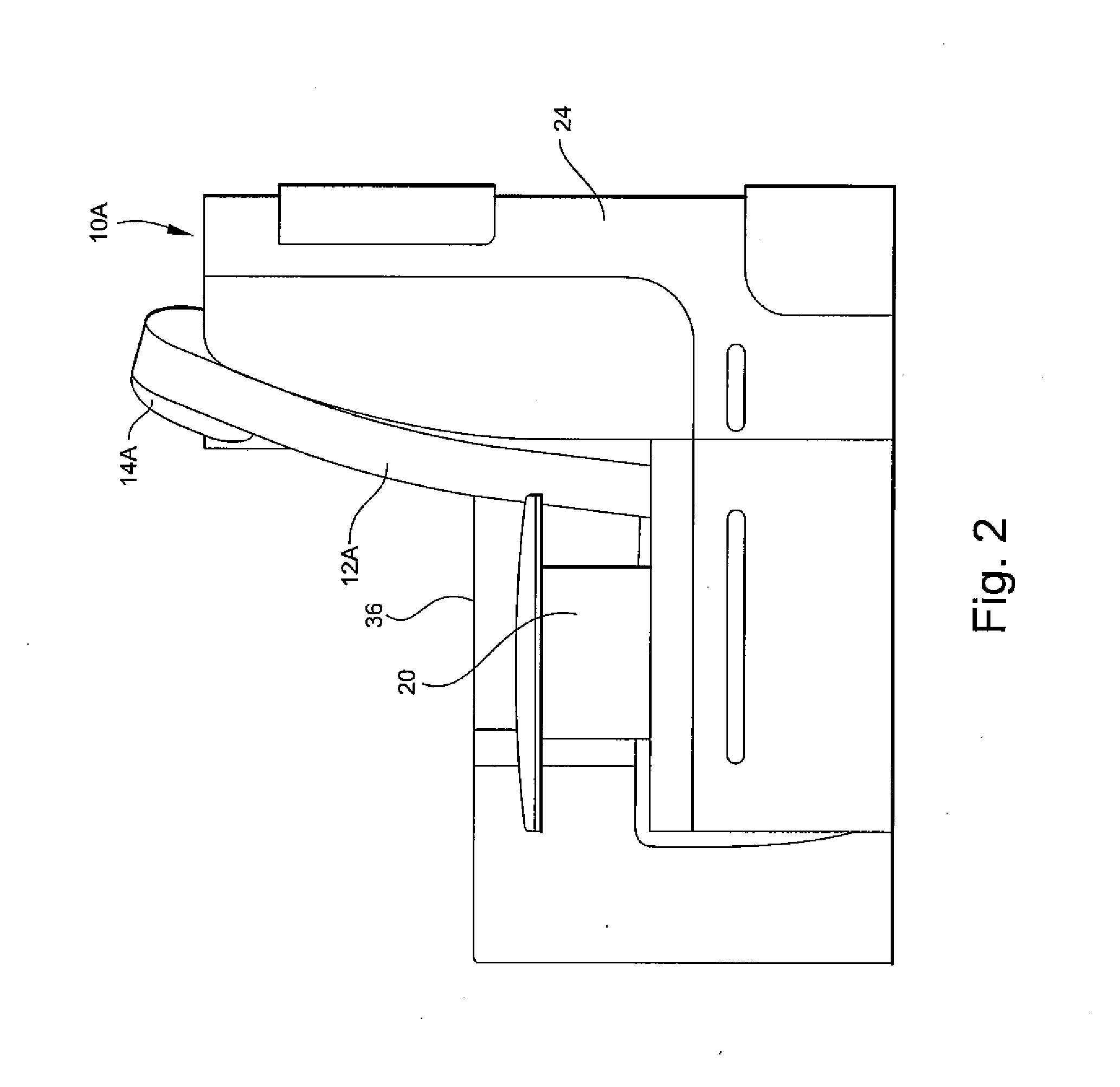
[0039]Referring to the drawings wherein identical reference numerals denote the same elements throughout the various views, FIGS. 1-7 illustrate a group of passenger seat units 10 which are arranged in seat pairs 11 each having first and mirror-image oriented seat units 10A and 10B with a center unit 13 disposed therebetween. The seat units 10 are substantially identical to each other, and include seat backs 12A, 12B (the upper portions of which define separate or integral headrests 14A, 14B) seat bottoms 16A, 16B, leg rests 18A, 18B, and spaced-apart arm rests 20, which may be movable between an “up” or “extended” position and a “down” or “retracted” position. The seat units 10 are supported by frames which are in turn mounted to the deck of the aircraft by track fittings of a known type.

[0040]Privacy shells 24 are provided which enclose the back and sides of the seat backs 12. The privacy shells 24 are configured to permit the occupant to see over and around the shells 24 when sit...


PUM


Abstract

The present invention provides an aircraft passenger seat assembly that includes: (a) first and second seats selectively movable between upright and reclined positions and adapted for being positioned beside and at inwardly-facing angles relative to each other; (b) a center console having a relatively wide aft end and a relatively narrow forward end for being positioned between the first and second seats; and (c) the relatively wide aft end of the center console including first and second foot wells therein adapted to permit the feet of a passenger seated in an aft-positioned first or second seat to extend therein when the aft-positioned first or second seat is in the recline position.

Description

BACKGROUND OF THE INVENTION[0001]This invention relates to passenger seating, and more particularly to an angled lounge seating arrangement.[0002]Long-haul aircraft flights regularly fly non-stop to destinations 12-18 hours or more away from the origination point. At present, first class cabins provide various forms of “sleeper seats”, meaning that the seat back reclines to the point where the seat occupant is able to attain a prone or nearly-prone position. In some cases the seats form a horizontal sleeping surface, and in other cases the head end of the reclined seat is raised to some degree above the foot end. The seats are generally parallel with the center line axis of the aircraft and traditionally forward facing in nature.[0003]While such seats provide good passenger comfort, there are deficiencies in this arrangement. Because aircraft operating costs are directly linked to the physical size and attendant aerodynamic draft of the fuselage, it is desirable to make the cabin as...

Claims


Application Information

Patent Timeline
Patent Type & Authority Applications(United States)
IPC IPC(8): A47C15/00B60N2/90
CPCB64D11/06B64D11/0604B64D11/0601B64D11/00153B64D11/0641B64D11/0606B64D11/0643B64D11/064
Inventor PLANT, TOMMY GEORGE
Owner BE AEROSPACE INCORPORATED
Learn More