Crystal Device and Method for Manufacturing Crystal Device

a crystal device and manufacturing method technology, applied in the field of crystal devices, can solve the problems of low accuracy and reliability, and the vibration wb>1/b> shown in fig. 14 becomes a very serious problem, and achieves the effects of high accuracy, stable vibration characteristics, and high reliability

a crystal device and manufacturing method technology, applied in the field of crystal devices, can solve the problems of low accuracy and reliability, and the vibration wb>1/b> shown in fig. 14 becomes a very serious problem, and achieves the effects of high accuracy, stable vibration characteristics, and high reliability

US20070247032A1Inactive Publication Date: 2007-10-25CITIZEN WATCH CO LTD

Image

  • Crystal Device and Method for Manufacturing Crystal Device
  • Crystal Device and Method for Manufacturing Crystal Device
  • Crystal Device and Method for Manufacturing Crystal Device

Examples


Embodiment Construction

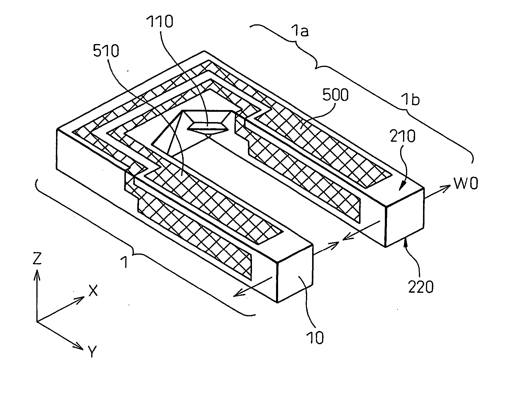
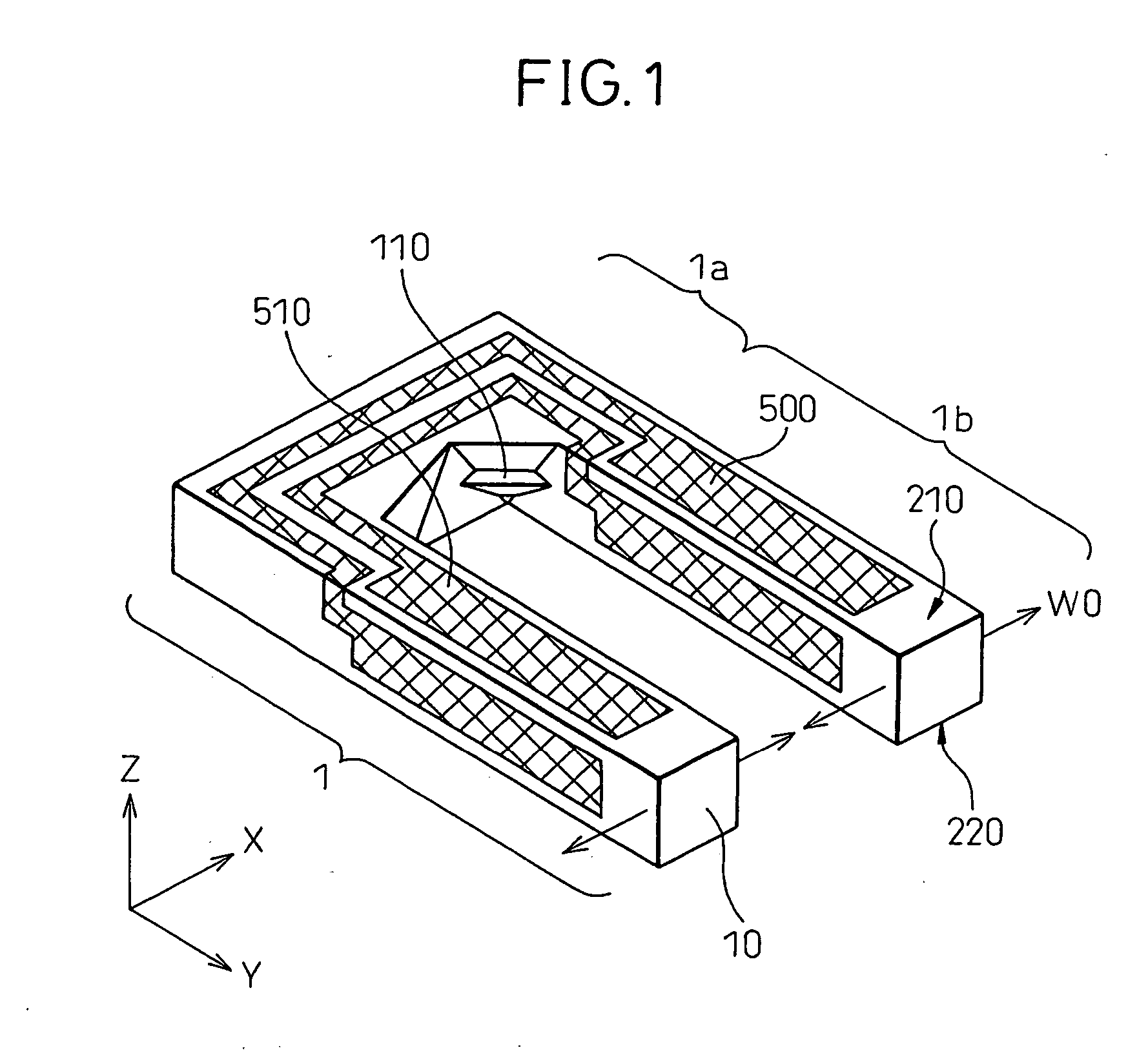
[0069]FIG. 1 is a diagram showing the structure of a crystal device 1 according to the present invention.

[0070] The crystal device 1 according to the present invention comprises a crystal plate 10 formed from a crystal, and electrodes 500 and 510. The crystal plate 10 is formed in the shape of a tuning fork which is made up of a base 1a and a plurality of vibrating prongs 1b protruding from the base 1a. The electrodes 500 and 510 are electrically separated from each other, and an electric field can be produced across the crystal plate 10 by applying different potentials to the respective electrodes. Since the crystal plate 10 is a piezoelectric material, the plate contracts or expands according to the direction of the applied electric field; this contracting / expanding motion causes the vibrating prongs 1b to vibrate. When a voltage is applied between the electrodes 500 and 510 of the crystal device 1, the two vibrating prongs 1b produce vibrations W0 along the X-axis direction.

[00...


PUM

PropertyMeasurementUnit
thicknessaaaaaaaaaa
thicknessaaaaaaaaaa
shapesaaaaaaaaaa

Abstract

An object of the present invention is to provide a crystal device that has stable vibration characteristics and that offers high reliability and high accuracy. The crystal device includes a first major face, which contains a portion of a base and a portion of a vibrating prong within a single plane, formed on the crystal plate, and a second major face, which contains another portion of the base and another portion of the vibrating prong within a single plane, formed on a crystal plate, wherein the first major face and the second major face have different outer shapes. The shapes of the first and second major faces can be produced by first forming mask layer patterns on a crystal substrate by exposure through different mask patterns and then etching the crystal substrate using the thus formed mask layer patterns.

Description

FIELD OF INVENTION [0001] The present invention relates to a crystal device comprising a base and a plurality of vibrating prongs protruding from the base, and a fabrication method for the same; more particularly, the invention relates to a tuning-fork type crystal gyro to be used as an angular velocity sensor, and a fabrication method for the same. BACKGROUND OF THE INVENTION [0002] With the widespread use of compact and high-accuracy products such as HDDs (Hard Disk Drives), mobile computers, portable telephones, car telephones, and other mobile communication apparatus in recent years, there has developed an increasing need to further enhance the reliability and accuracy of crystal devices, typically crystal oscillators, used in these products. [0003] The need for increased reliability and increased accuracy has been growing, among others, for crystal gyros used for angular velocity detection in navigation systems or for camera shake control in video cameras. [0004]FIG. 14 is a di...

Claims


Application Information

Patent Timeline
25 Oct 2007
Publication
US20070247032A1
IPC
H03H9/21; H01L41/22; H01L41/09; H01L41/18; H01L41/332; H03H3/02; H03H9/19; H03H9/215
CPC
H03H3/02; Y10T29/42; H03H9/21
Inventors
IKEDA, TOMOO