
Switching power supply apparatus and method

a technology of electrical power supply and power supply device, which is applied in the direction of power conversion system, dc-dc conversion, instruments, etc., can solve the problems of causing uncomfortable tingling or prickling, and achieve the effect of reducing or preventing the hum generated, reducing the impedance of external equipment, and reducing the hum

Inactive Publication Date: 2007-10-25
ROLAND CORP
View PDF6 Cites 14 Cited by
  • Summary
  • Abstract
  • Description
  • Claims
  • Application Information

AI Technical Summary

Benefits of technology

[0013] With the type of switching electrical power source device that was described above, it is possible to eliminate a constant line noise, but there is still a hum present that comes from the commercial alternating current power source. The hum can be mixed in with the sound that is output from the speakers when this electric power is supplied. In such audio equipments, the ground of the secondary circuit is connected to a metal panel. Because there is a minute shocking current that is lower than the leakage current limit value that is demanded by safety regulations, when the metal panel is touched, a weak shock can occur that imparts an uncomfortable tingling or prickling feeling.
[0014] According to certain embodiments of the invention described herein, both the hum and the weak shocks can be reduced.
[0019] A first embodiment as described above, has an advantage that it can reduce or prevent the hum that is generated in audio equipment to which an electric power is supplied. Furthermore, the weak shock that are provided when the metal panel of the equipment is touched, can be further reduced. Because the ground on the secondary side is connected to the ground of the external equipment that is connected on the secondary side, the impedance of the external equipment is lowered due to the fact that the first and second capacitors are connected to the ground on the secondary side. Therefore, the first embodiment presented above not only can reduce the hum, but it can also reduce the leakage current due to the switching noise.
[0020] According to a second embodiment as described above, in addition to having the same advantages as was outlined by the first embodiment, it can also improve the reduction of common mode noise. By making the capacitance of the first capacitor and the second capacitor the same, a hypothetical midpoint potential is formed at the connection point of the first capacitor and the second capacitor. Because the connection point is connected to the ground conductor on the secondary side, the impedance of the ground on the secondary side can be reduced.
[0021] According to a third embodiment as described above, in addition to having the advantages outlined for the other embodiments there is the advantage that it is possible to reduce the switching noise that is generated on the primary side.

Problems solved by technology

Because there is a minute shocking current that is lower than the leakage current limit value that is demanded by safety regulations, when the metal panel is touched, a weak shock can occur that imparts an uncomfortable tingling or prickling feeling.

Method used


Image

  • Switching power supply apparatus and method
  • Switching power supply apparatus and method
  • Switching power supply apparatus and method

Examples


Embodiment Construction

[0024] Example embodiments of the present invention are described here in detail with reference to the attached drawings.

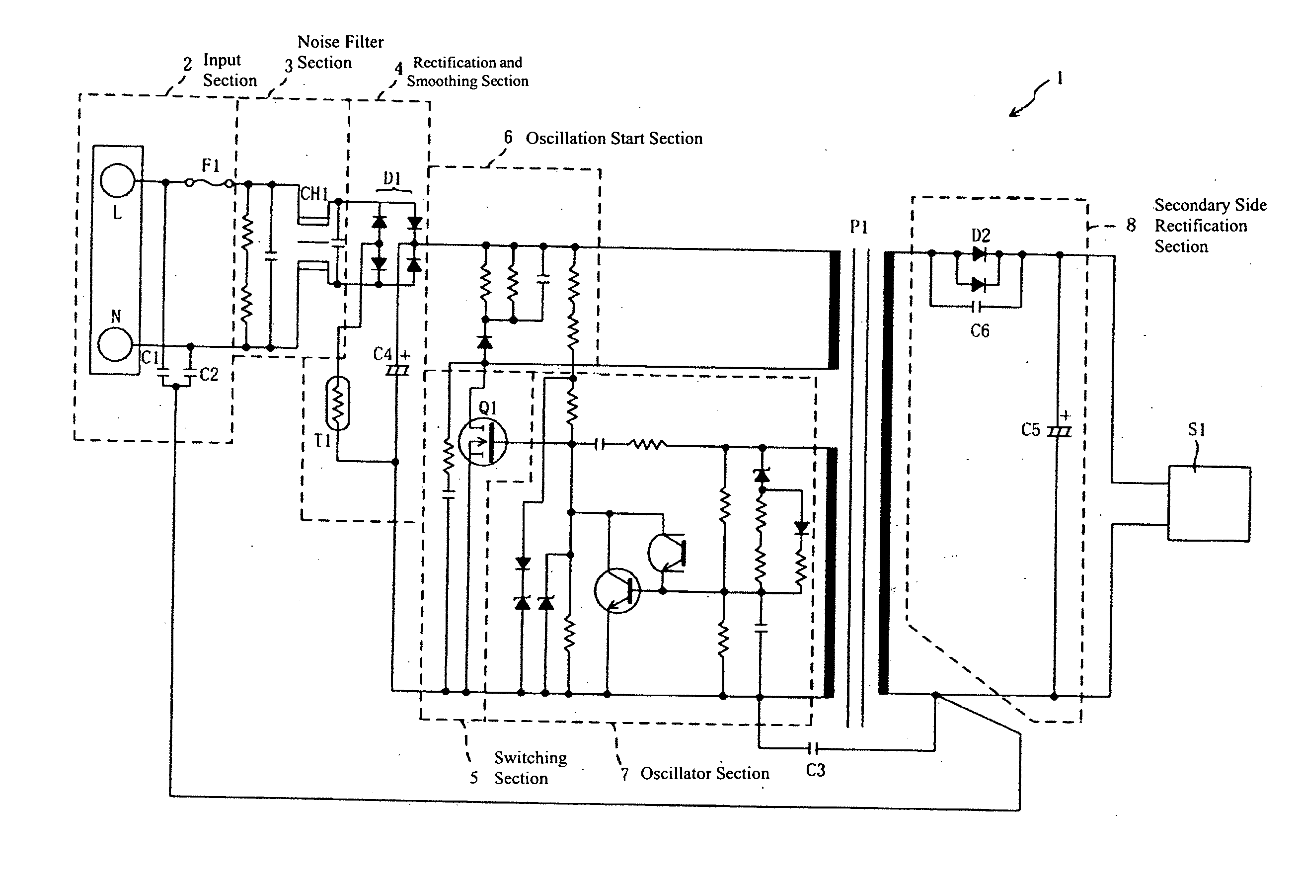
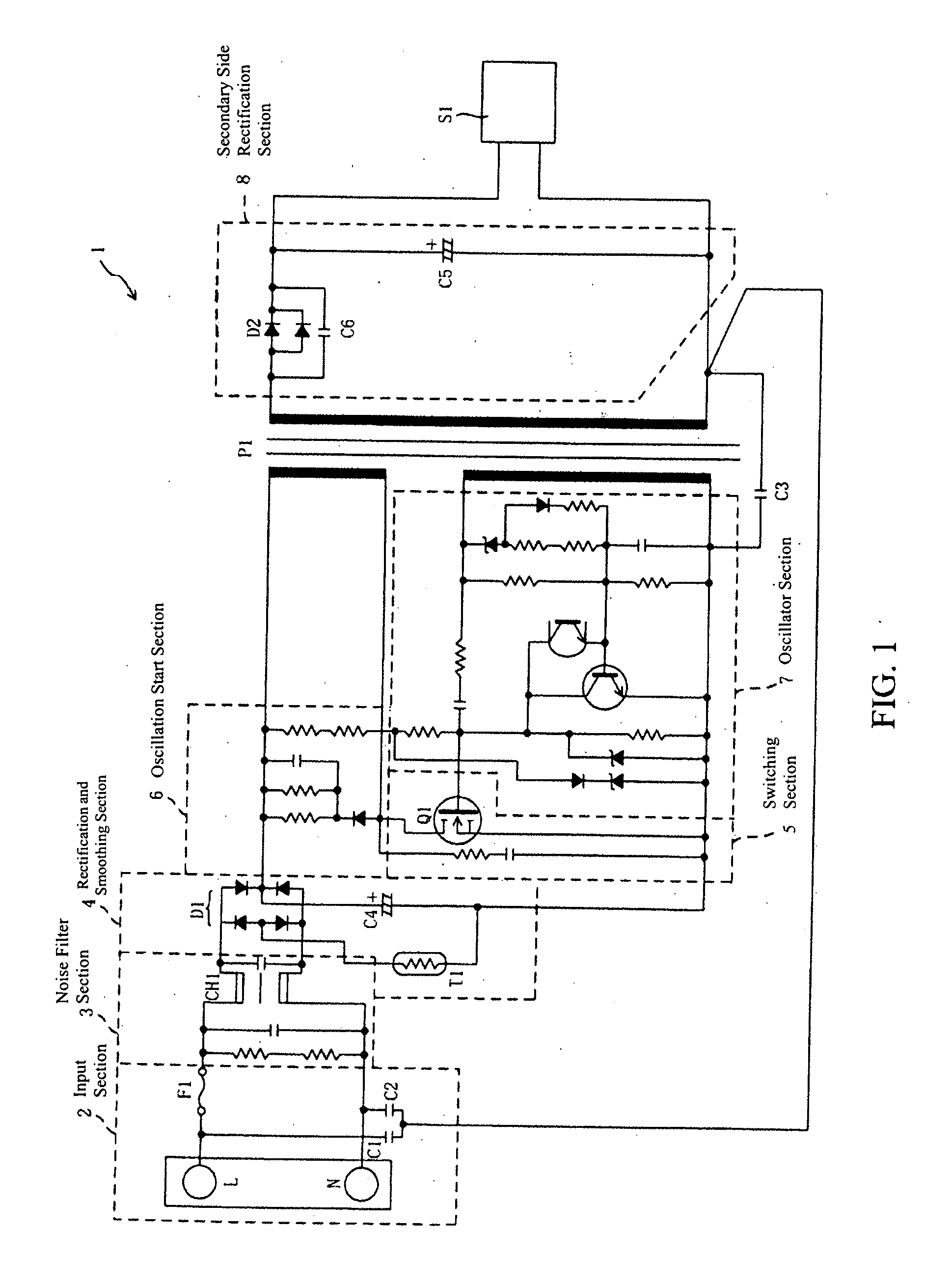
[0025]FIG. 1 is a block diagram that shows an electrical configuration of a switching electrical power source device 1, according to a first embodiment of the present invention. As is shown in FIG. 1, the switching electrical power source device 1 includes an input section 2, a noise filter section 3, a rectification and smoothing section 4, a switching section 5, an oscillation start section 6, an oscillator 7, a transformer P1, and a secondary side rectification section 8.

[0026] An alternating current voltage that is input to the input section 2, an output on the line of the external noise that is entered from the input side, and a noise that is generated by the switching section 5, are filtered by the noise filter section 3. After being rectified and smoothed by the rectification and the smoothing section 4, the voltage is switched by the switching section 5 ...


PUM


Abstract

Configurations provide reduction in the hum and the weak shocks that are produced in audio equipments where electrical power is supplied. Switching electrical power sources include, a rectification element that rectifies a current that is supplied, a switching element that switches the input voltage that has been rectified by the rectification element, an oscillator circuit that oscillates at a specified frequency and drives the switching element by means of oscillation, and a transformer with which the voltage that has been switched by the switching element is input to the primary coil and. wherein an electrical power source output is obtained from a secondary coil. A plurality of capacitors are connected to the conductors.

Description

CROSS-REFERENCE TO RELATED PATENT APPLICATIONS [0001] The present invention relates to Japan Patent Application 2006-117332, filed on Apr. 21, 2006, which is incorporated herein by reference in its entirety and which forms a basis for priority. BACKGROUND OF THE INVENTION [0002] 1. Field of the Invention [0003] Embodiments of the present invention relate to switching electrical power source devices and methods, and in particular to such devices and methods that reduce the hum that is produced in audio equipment. [0004] 2. Description of the Related Art [0005] In recent years, there has been a significant progress in the computerization of control systems for switching electrical power source devices. They have become lighter and smaller, and are widely used as the electrical power sources for electronic and electrical devices. An important problem that has been studied involves designing circuits with switching electrical power sources in which the Electro-Magnetic Interference (EMI...

Claims


Application Information

Patent Timeline
Patent Type & Authority Applications(United States)
IPC IPC(8): G05F3/00
CPCH02M1/44H02M2001/123H02M3/335H02M1/123
Inventor IWAMOTO, HOICHIEMOTO, HIROSHI
Owner ROLAND CORP
Learn More