
Branching filter

a filter and filter body technology, applied in the field of branching filters, can solve the problems of unfavorable ripple at the high frequency side and more likely a large ripple, and achieve the effect of increasing attenuation and sufficient pass band width

Active Publication Date: 2007-10-25
MURATA MFG CO LTD
View PDF12 Cites 6 Cited by
  • Summary
  • Abstract
  • Description
  • Claims
  • Application Information

AI Technical Summary

Benefits of technology

[0008] In order to overcome the problems described above, preferred embodiments of the present invention provide a branching filter including a first band-pass filter having a relatively low frequency passband and a second band-pass filter having a relatively high frequency passband, each having a SAW filter having a ladder circuit structure, the branching filter not only increasing the attenuation at the low frequency side of the passband of the second band-pass filter, but also suppressing the occurrence of a ripple at the high frequency side of the passband of the first band-pass filter, thereby achieving a sufficient pass band width.

Problems solved by technology

However, when a polar filter, such as the SAW filter 101, is used as a band-pass filter having a relatively high frequency passband in a branching filter, it has been known that an undesired ripple occurs at the high frequency side of the passband of the other band-pass filter having a low frequency passband.
However, the larger the inductance, the more likely a large ripple occurs in skirt characteristics at the low frequency side of the passband.

Method used


Image

  • Branching filter
  • Branching filter
  • Branching filter

Examples


first preferred embodiment

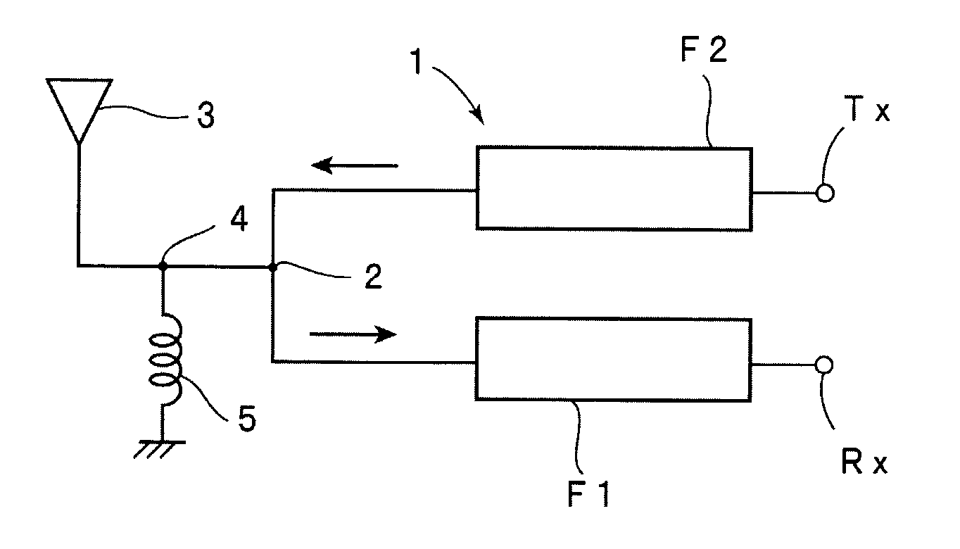
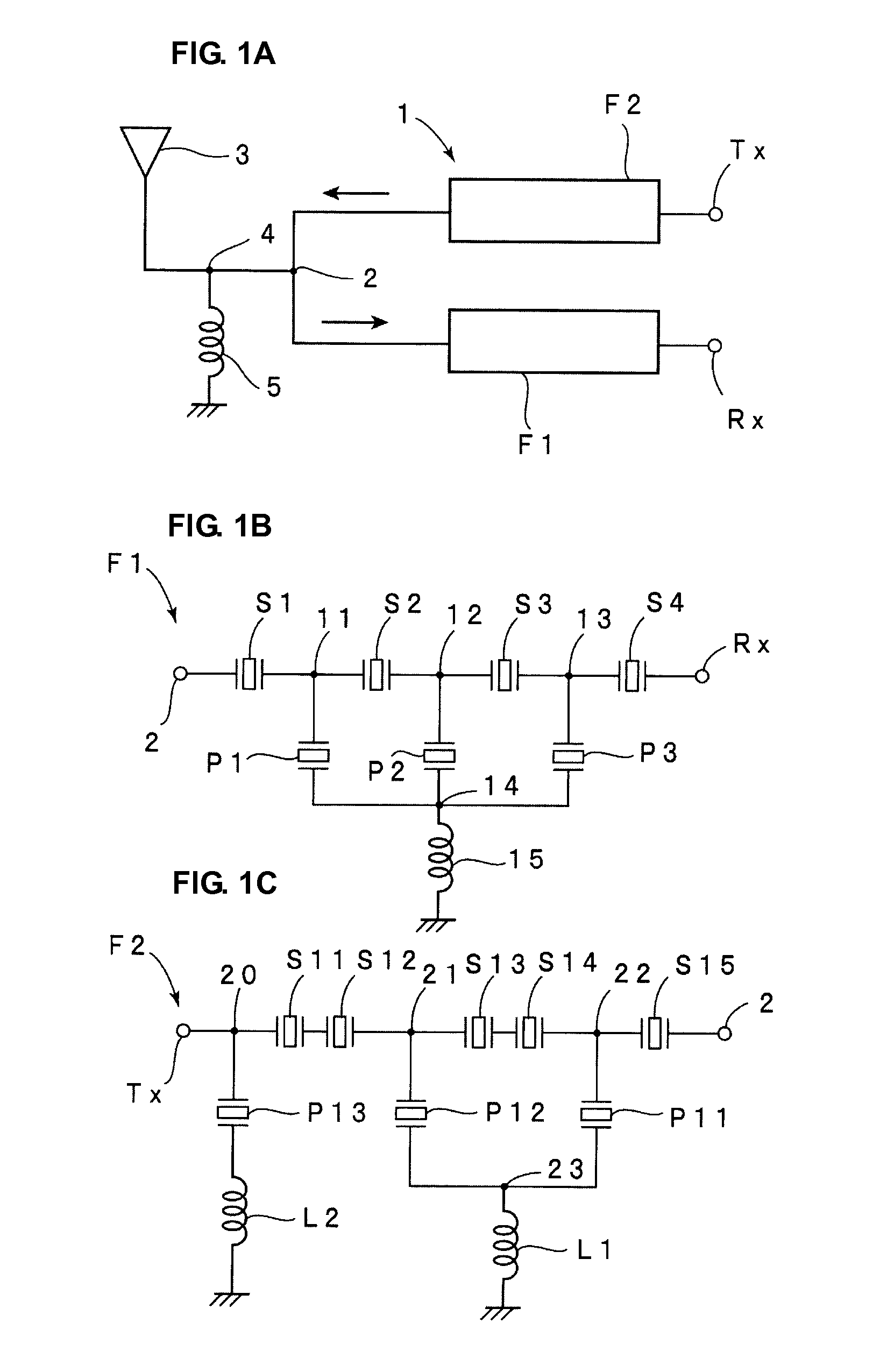
[0038]FIG. 1A is a block diagram showing a schematic structure of a branching filter according to a first preferred embodiment of the present invention, and FIG. 1B and FIG. 1C are circuit diagrams of a first band-pass filter F1 serving as a reception-side band-pass filter according to the first preferred embodiment and a second band-pass filter F2 serving as a transmission-side band-pass filter according to the first preferred embodiment, respectively.

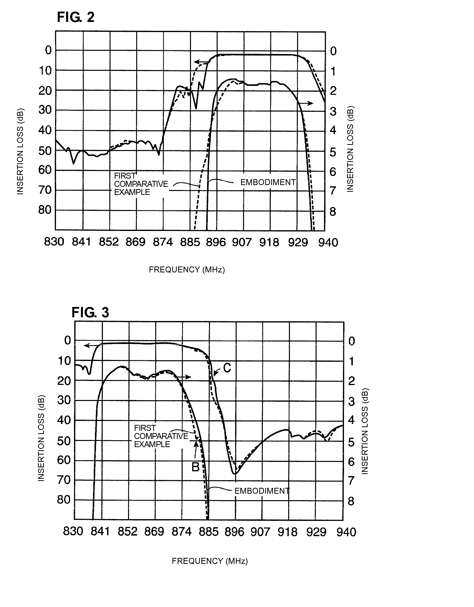
[0039] A branching filter 1 of the first preferred embodiment is preferably a branching filter for a CDMA-800 cellular phone used in Japan. The branching filter according to this standard has a transmission-side passband of 898-925 MHz and a reception-side passband of 843-870 MHz. Thus, the transmission-side passband is higher than the reception-side passband.

[0040] As shown in FIG. 1A, the branching filter 1 preferably includes the first and second band-pass filters F1 and F2. The first band-pass filter F1 is the reception-side ban...

second preferred embodiment

[0074] A branching filter of a second preferred embodiment has a circuit structure similar to that of the branching filter 1 of the first preferred embodiment. Therefore, the description of the circuit structure shown in FIGS. 1A to 1C is applied to the branching filter of the second preferred embodiment. In the second preferred embodiment, as will be shown in Table 2 below, the parallel resonators P12 and P13 of the second band-pass filter F2 have the equal duty, though they have different wavelengths. Other than these points, the branching filter of the second preferred embodiment has the same structure as the branching filter 1 of the first comparative example, which has been given as a comparative example to the first preferred embodiment described above.

[0075] Filter characteristics of the above-structured branching filter of the second preferred embodiment and filter characteristics of the branching filter of the first comparative example described above are shown in FIGS. 5 ...


PUM


Abstract

A branching filter suppresses the effect of a ripple at a high frequency side of a first band-pass filter having a relatively low frequency passband and achieves sufficient pass band widths of the first and second band-pass filters. The branching filter includes a first band-pass filter having a relatively low frequency passband and a second band-pass filter having a relatively high frequency passband. The first and second band-pass filters each have a SAW filter having a ladder circuit structure. The second band-pass filter has first to third parallel resonators. The first and second parallel resonators are commonly connected to a common-connection ground terminal. A first inductance is connected between the common-connection ground terminal and a ground potential. In the branching filter, a relationship f1>f0>f2 is satisfied, wherein f0 denotes an average of resonant frequencies of all the parallel resonators.

Description

FIELD OF THE INVENTION [0001] The present invention relates to branching filters used in mobile communication devices, such as cellular phones, and more particularly, to a branching filter including a surface acoustic wave (SAW) filter having a ladder circuit structure. DESCRIPTION OF THE RELATED ART [0002] Band-pass filters including SAW filters are widely used in, for example, mobile communication devices, such as cellular phones, for the purpose of miniaturization. An exemplary SAW filter of this type is disclosed in Japanese Unexamined Patent Application Publication No. 10-200370 described below. FIG. 13 is a circuit diagram of a SAW filter described in Japanese Unexamined Patent Application Publication No. 10-200370. [0003] A SAW filter 101 has a ladder circuit structure including series resonators Sa and Sb and parallel resonators Pa to Pc. [0004] In the above-described SAW filter 101, the parallel resonator Pa is connected to a ground potential with an inductance I1 interpose...

Claims


Application Information

Patent Timeline
Patent Type & Authority Applications(United States)
IPC IPC(8): H03H9/72
CPCH03H9/0576H03H9/725H03H9/72H03H9/6483
Inventor TAKATA, TOSHIAKI
Owner MURATA MFG CO LTD
Learn More