Method of reducing false alarms during auto-arm

a technology of automatic arming and false alarms, applied in the direction of alarms, instruments, etc., can solve the problems of security system delaying the automatic arming process, and achieve the effect of reducing false alarms and reducing false alarms

Active Publication Date: 2007-10-25
ADEMCO INC
View PDF4 Cites 52 Cited by
  • Summary
  • Abstract
  • Description
  • Claims
  • Application Information

AI Technical Summary

Benefits of technology

[0009] Accordingly, provided is a method for reducing false alarms for a security system when the security system is programmed to automatically arm the security system. The method reduces false alarms by preventing the security system to auto-arm the system in away mode based upon certain detected events within the premises. The method comprise the steps of determining if a current time equals or is within a predetermined detection period, judging whether at least one of a plurality of motion sensors have detected an event within a protected area during the predetermined detection period, determining if a premises exit signal has been generated within a predetermined period from said detected movement, generating an automatic arm adjustment signal based upon said detected event and the premises edit signal; and executing a modification to the programmed automatic arm based upon the automatic arm adjustment signal. The method will also notify the owner that the auto-arm mode failed.

Problems solved by technology

However, if the sensor is an exterior sensor, the event can be the opening or closing of a door or window or the breakage of glass within a window.
Alternative, if both the event is detected and no premises exit signal has been generated, the security system can delay the automatic arm process.

Method used


Image

  • Method of reducing false alarms during auto-arm
  • Method of reducing false alarms during auto-arm
  • Method of reducing false alarms during auto-arm

Examples


first embodiment

[0030] In the first embodiment, if the system detects both motion and no premises exit, then the system will cancel the auto-arm process. A premises exit is a signal that indicates that one of a plurality of predefined doors has been opened, in an entry / exit zone. This signal means that a person has left the premises.

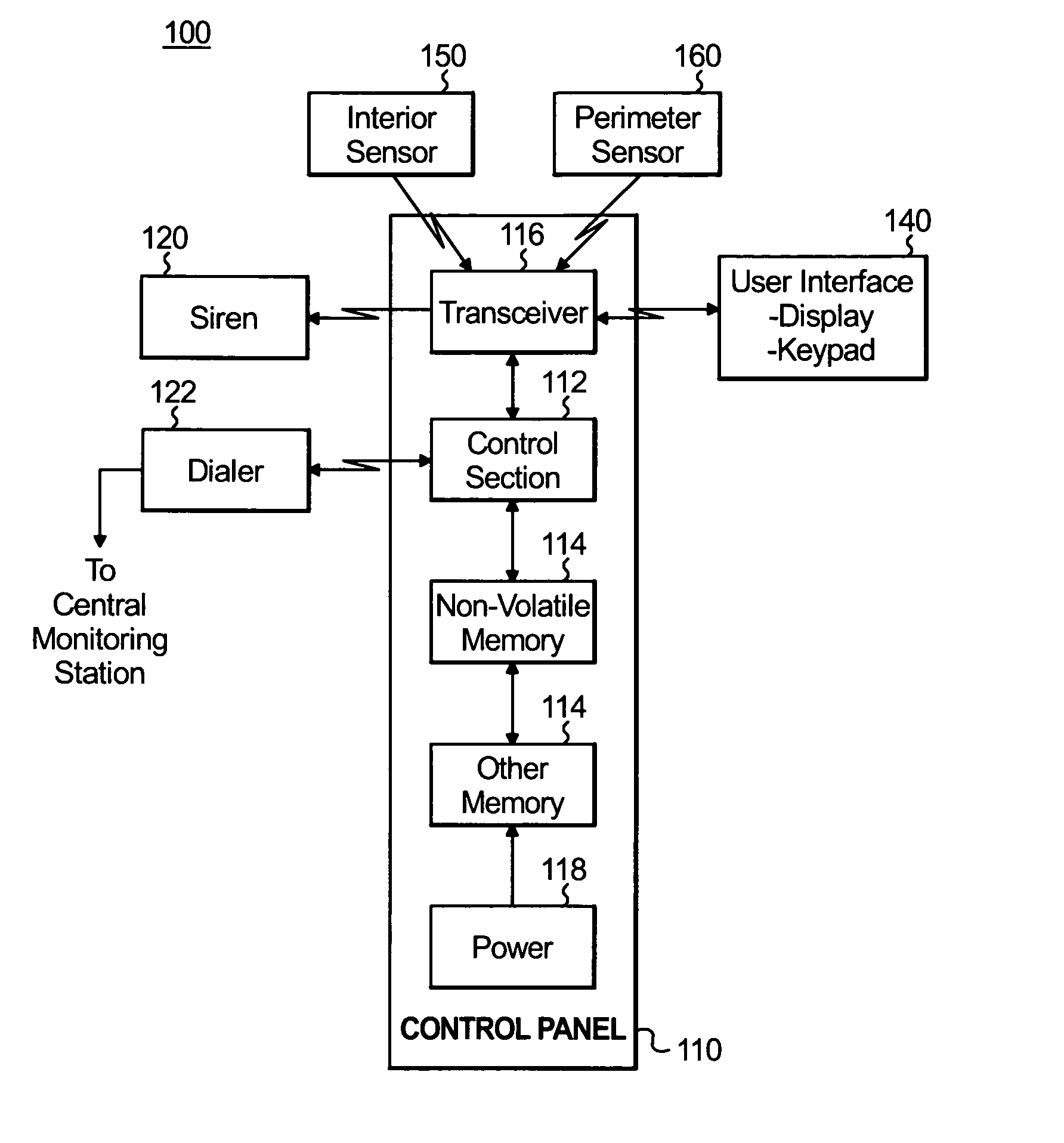
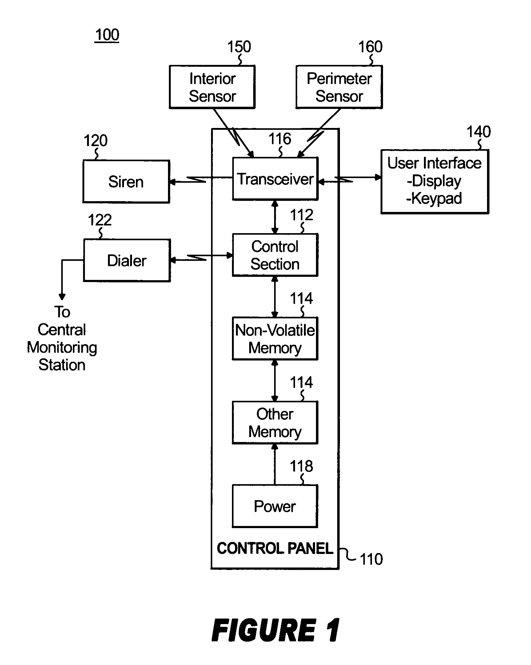
[0031] At step 300, the control panel 110 will determine if the user has programmed or scheduled an automatic arm of the away mode (hereinafter “Auto-Arm Away”). If the result of the determination is “yes” then the control panel 110 will determine the current time, at step 305. An internal clock within a microcontroller 112 maintains the current time. The current time is compared, using a comparison means, with the predefined detection period or Auto-Arm warning period, at step 310. The Auto-Arm warning period is the time period where the system can warn the user that the system is about automatically arm itself. The period of time is directly prior to the auto-arm time...

second embodiment

[0036] if the system detects both motion and no premises exit, then the system can prevent the system from executing the auto-arm away mode, but rather executing an auto-arm stay mode depending on the location of the detected motion.

[0037]FIG. 4 illustrates the method of reducing false alarms according to the second embodiment of the invention. Steps 300-330 are the same as in the first embodiment and will not be described again.

[0038] In the second embodiment, instead of just canceling the auto-arm function if both motion is detected and no premises exit was detected, the control panel 110 will determine the location of the detected motion and based upon this determination, either cancel the auto arm away (and stay) or allow an auto-arm stay. By allowing for the execution of an auto-arm stay at least part of the security system 100 is armed and some protection is provided.

[0039] The control panel 110 will prevent the system from executing the auto-arm away mode if the perimeter ...

third embodiment

[0041] In the third embodiment, the control panel 110 will cancel the scheduled auto-arm away immediately if any motion is detected during the predefined detection period or auto-arm warning period. No premises exit signal is needed. No type of auto-arming will occur.

[0042]FIG. 5 illustrates the false alarm reducing method according to the third embodiment. Steps 300-320 are the same as the first two embodiments and will not be described. As illustrated in FIG. 5, steps 325 and 330 are eliminated. If any motion is detected the process proceeds directly to step 335. The scheduled auto-arm away mode is cancelled.

[0043]FIG. 6 illustrates the false alarm reducing method according to the fourth embodiment of the invention. Steps 300-330 are the same as the first two embodiments and will not be described again. According to the fourth embodiment of the invention, the auto-arm function can be delayed if motion is detected and a premises exit signal was not detected. The delay of the auto ...


PUM


Abstract

A method for reducing false alarms for a security system when the security system is programmed to automatically arm the security system. The method reduces false alarms by preventing the security system to auto-arm the system in away mode based upon certain detected events within the premises. The method comprise the steps of determining if a current time equals or is within a predetermined detection period, judging whether at least one of a plurality of motion sensors have detected an event within a protected area during the predetermined detection period, determining if a premises exit signal has been generated within a predetermined period from said detected movement, generating an automatic arm adjustment signal based upon said detected event and the premises edit signal; and executing a modification to the programmed automatic arm based upon the automatic arm adjustment signal. The method will also notify the owner that the auto-arm mode failed.

Description

BACKGROUND OF THE INVENTION [0001] 1. Field of Invention [0002] The invention relates to a method for reducing false alarms generated by a security system located in a commercial or residential property. More particularly, the invention is related to a method for reducing false alarms where a security system is programmed to automatically arm the security system at a predetermined time schedule and at least one person is still within the premises. [0003] 2. Background [0004] Security systems, such as for homes and businesses, have become commonplace as people seek to protect themselves and their property. A security system includes any life, safety, and property protection system. A security system typically includes an installed security system and a central monitoring station. The installed security system includes a control panel, a user interface device and a plurality of sensors. The sensors can includes smoke, carbon monoxide, motion, and burglary. There are perimeter and inte...

Claims


Application Information

Patent Timeline
Patent Type & Authority Applications(United States)
IPC IPC(8): G08B29/00
CPCG08B29/24G08B25/008
Inventor MARTIN, CHRISTOPHER D.
Owner ADEMCO INC
Why Eureka
Try Eureka