

Dual detector with transverse coils
a transverse coil and detector technology, applied in the field of detection of target objects, can solve the problems of insufficient training of operators using these detectors, inability to hold the detector properly, and inability to detect objects properly, so as to reduce false alarms and improve sensitivity
- Summary
- Abstract
- Description
- Claims
- Application Information
AI Technical Summary
Benefits of technology
Problems solved by technology
Method used
Image

Examples
Embodiment Construction
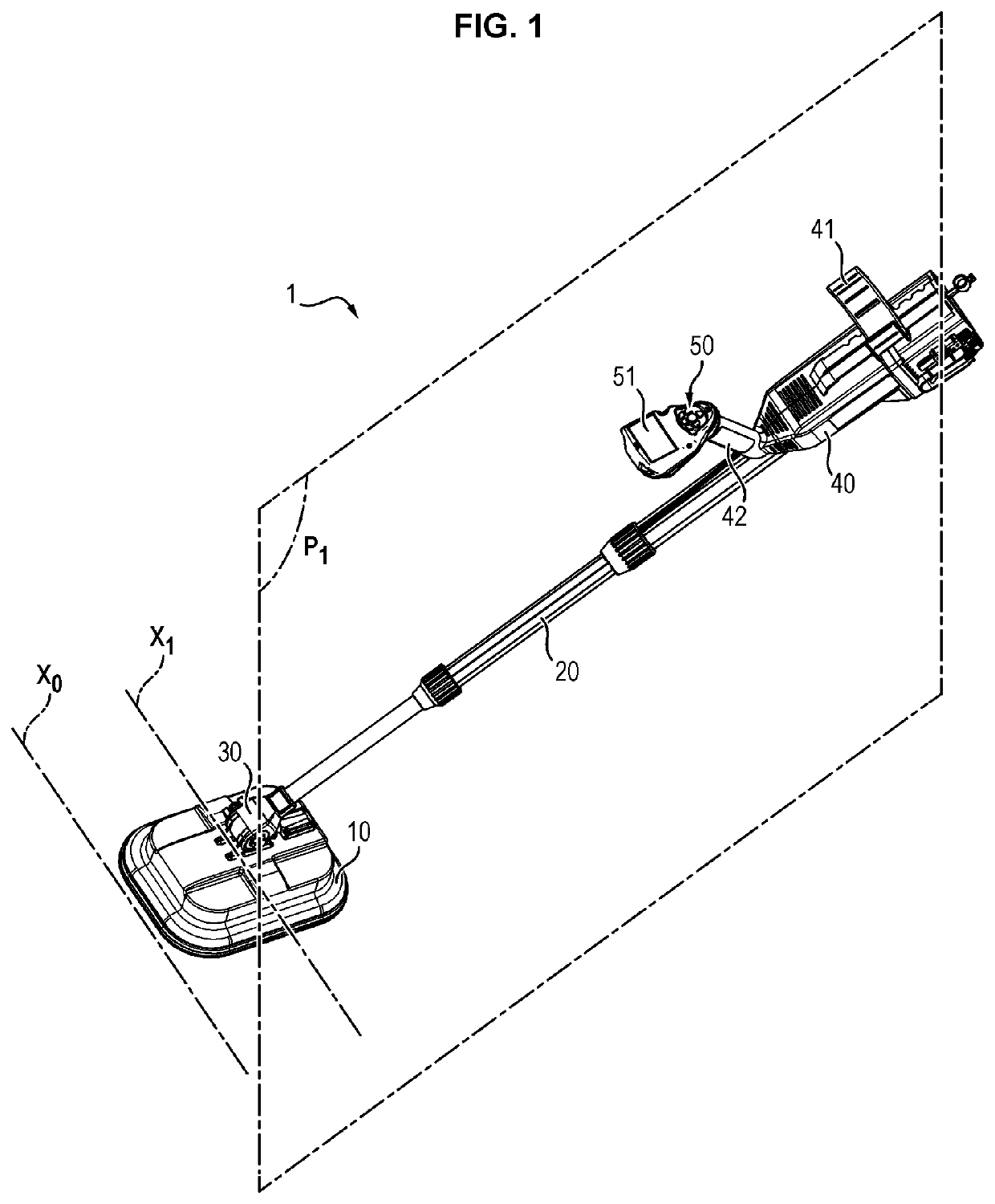
[0044]A dual detector 1 according to the invention comprises a detection head 10 fixed to a handle 20 by means of a mechanical link 30.
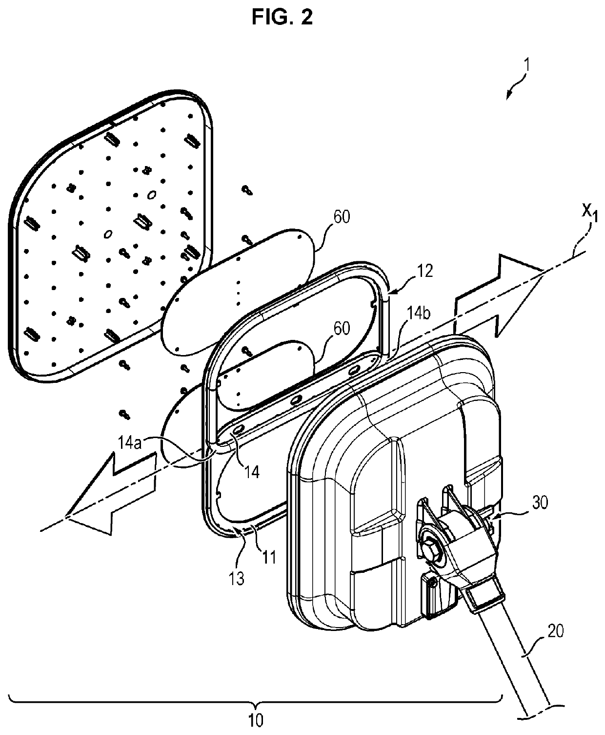
[0045]The detection head 10 corresponds to the portion intended to come close to the ground in order to detect target products. To this end, it comprises:
[0046]a platform 11
[0047]an inductive sensor fixed to the platform 11 and comprising a transmitting coil 12 and a receiving coil 13 distinct from each other, and
[0048]another sensor, preferably a ground-penetration radar.
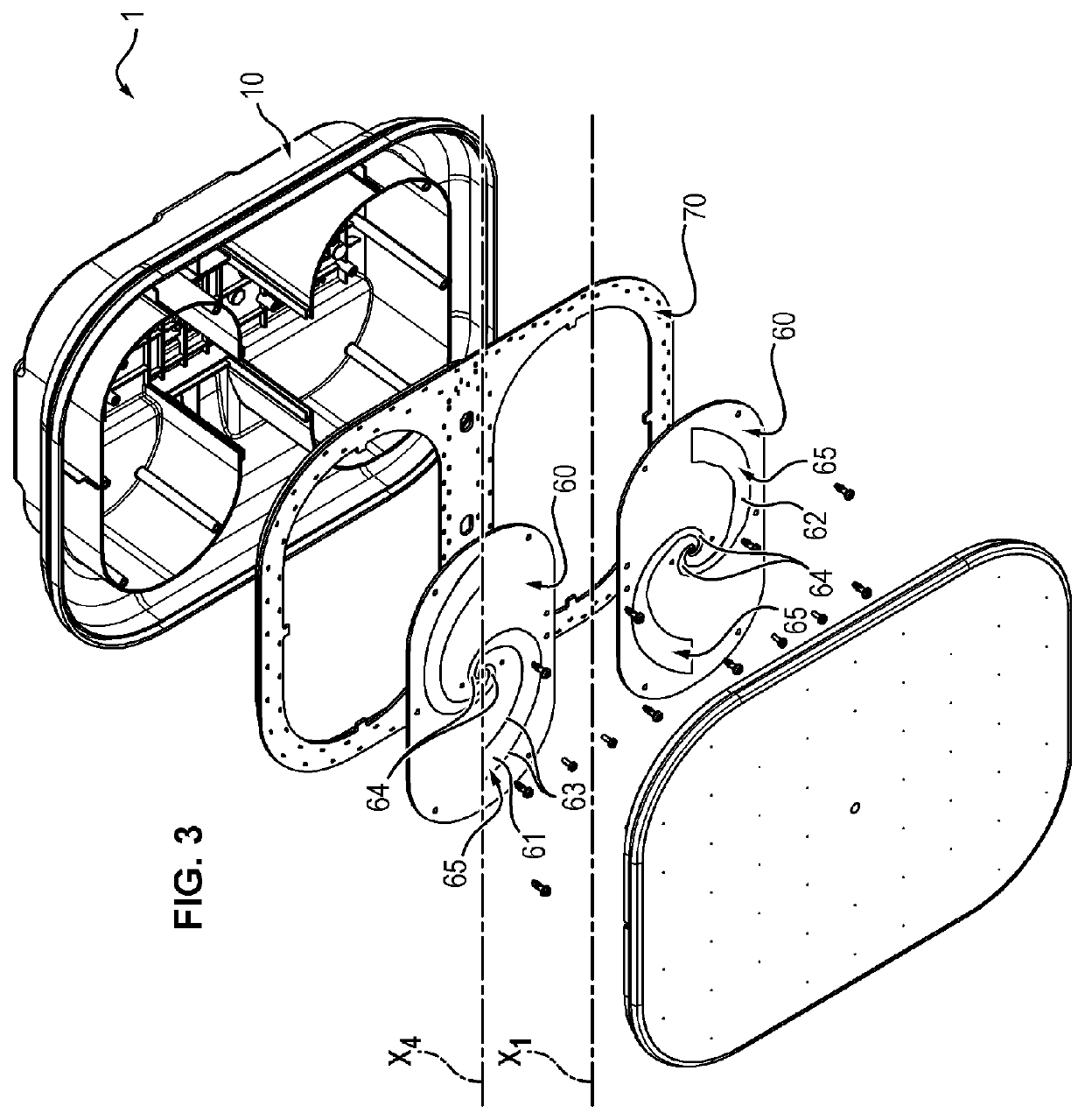
[0049]The transmitting coil 12 and the receiving coil 13 are homopolar windings. In a manner known per se, they are configured to transmit and receive waves having a frequency comprised between 300 Hz and 180 kHz. They each form a loop and are shaped so that the loop of the transmitting coil 12 at least partially overlaps the loop of the receiving coil 13 so as to form a coupling area 14. This configuration allows obtaining an inductive sensor in which mutual inductance is minimal.
[...
PUM
 Abstract
Description
Claims
Application Information