
Integrated lightning detector

a detector and integrated technology, applied in the field of security systems, can solve the problems of false alarm, false alarm, false alarm in security detectors,

Inactive Publication Date: 2005-11-01
JOHNSON CONTROLS TYCO IP HLDG LLP
View PDF8 Cites 8 Cited by
  • Summary
  • Abstract
  • Description
  • Claims
  • Application Information

AI Technical Summary

Benefits of technology

[0028]A method of reducing false alarms in a security alarm systems having an alarm panel which processes signals received from a series of detectors includes the steps of using a receiving circuit of the alarm control panel to detect an electromagnetic signal indicative of lightning and upon detection of an electromagnetic signal indicative of lightning, interrupting normal operation of the security alarm system by temporarily ignoring any signals received from the series of remote sensors, or reporting together with a detected alarm condition, the detection of an electromagnetic signal indicative of lightning.

Problems solved by technology

Lightning produces a broadband electromagnetic signal which produces a signal in the detector or causes a change in the monitored space leading to a false activation of the detector.
Thunder associated with lightning can also cause a large acoustic signal which can lead to false alarms.
Lightning and thunder are two examples of naturally occurring events which produce high energy which can lead to false alarms in security detectors.
Processing of each false alarm incurs a certain expense but more importantly, it also reduces the confidence that a reported alarm condition is in fact an alarm condition which requires prompt investigation.
Unfortunately, this arrangement requires each motion detector to include additional redundant circuitry and additional processing of the signals from the two different circuits.
This significantly adds to the cost of each sensor, thereby increasing the cost of the overall system.
It has been recognized that certain natural occurring events produce electromagnetic interference or radio frequency interference which negatively affect the performance of motion detectors and security systems.

Method used


Image

  • Integrated lightning detector
  • Integrated lightning detector
  • Integrated lightning detector

Examples


Embodiment Construction

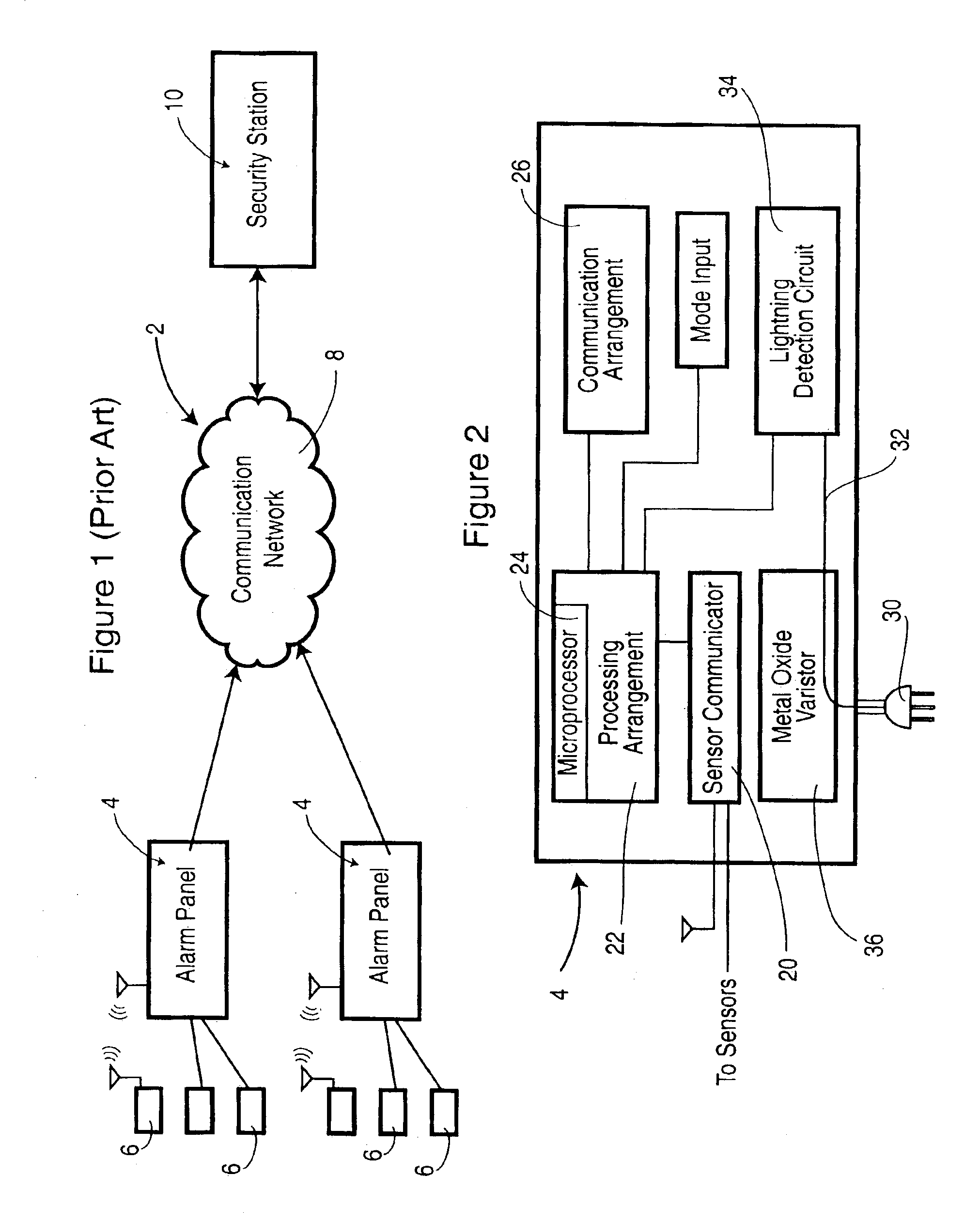
[0035]The schematic view of FIG. 1 shows two alarm panels 4 communicating through a network 8 such as the cellular telephone network or public switched telephone network with the security station 10. Each of the alarm panels 4 has a series of detectors 6 which provide information to the alarm panel regarding the status of the monitored space. The detectors 6 can include, for example, different types of motion detectors, glass break detectors, and contact switches. These types of detectors can be hard wired to the alarm panel 4 or can communicate with the alarm panel by wireless communication.

[0036]In wireless communication, typically the wireless detector 6 will transmit alarm information or status signal to the alarm panel on a predetermined basis. For cost reasons, the wireless communication is typically not a two way communication. There are a host of security systems which operate in the manner of FIG. 1.

[0037]The individual detectors 6 can be sensitive to electromagnetic interf...


PUM


Abstract

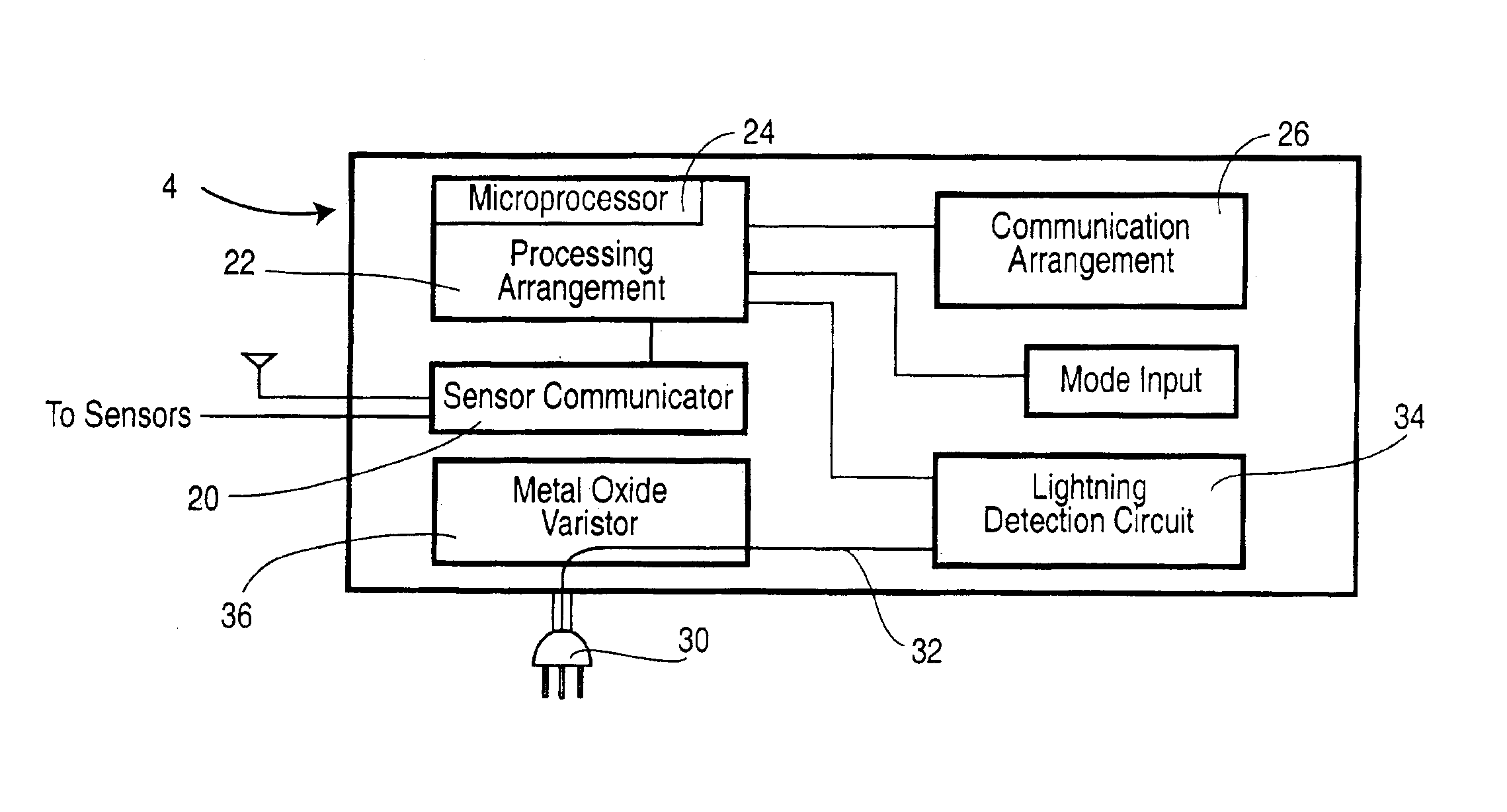
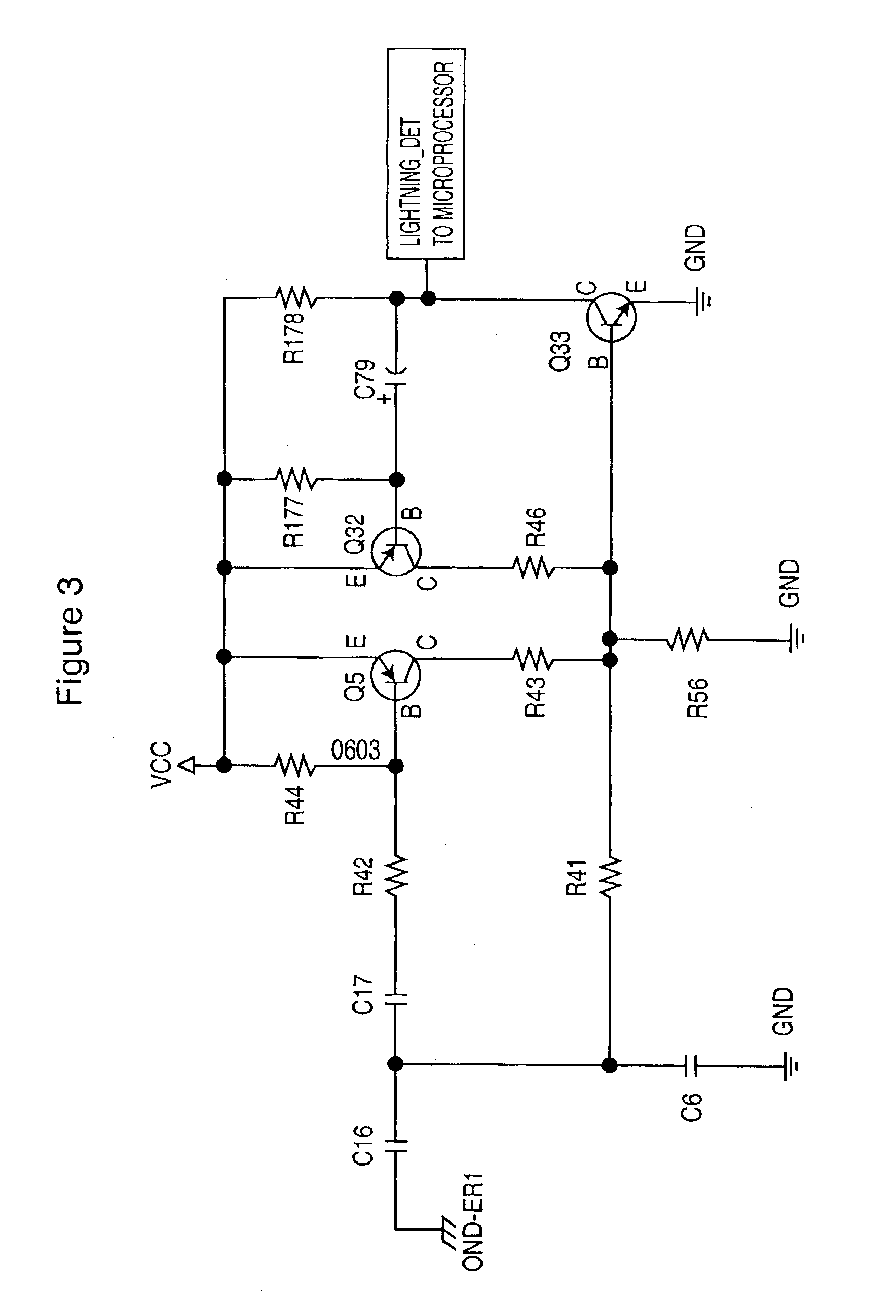
An alarm panel of a security system is additionally provided with an interference circuit for evaluating the possible presence of a large electromagnetic interference signal such as lightning. The earth ground connection of the alarm panel to a power source is used to provide an input to the interference circuit. The earth ground connection receives large transient signals caused by such naturally occurring events. The alarm panel uses this additional information to modify the reporting of alarm conditions. This has particular application for addressing problems associated with motion detectors falsely triggering when a large electromagnetic signal is received. The solution of the alarm panel sensing this condition in contrast to each detector sensing this condition is more reliable, allows combining of detector information and is more cost effective.

Description

FIELD OF THE INVENTION[0001]The present invention relates to security systems, and in particular, to alarm panels and the determination and processing of signals and the subsequent reporting to a security station.BACKGROUND OF THE INVENTION[0002]It is now common for businesses and homeowners to have a security system for reporting of alarm conditions to a security station. One of the primary functions of such a security system is to provide an alarm report to the security station when the owner is absent and one or more of the detectors reports an alarm condition. The type of detectors vary from relatively simple hard wired detectors, such as door or window contacts, to more sophisticated battery operated sensors such as motion and glass break detectors.[0003]The security alarm system located in the premise being protected includes a series of different types of sensors all of which report to an alarm control panel. The control panel is typically installed in a safe location and is ...

Claims


Application Information

Patent Timeline
IPC IPC(8): G08B29/00G08B29/18
CPCG08B29/18
Inventor PARKER, JAMESPILDNER, REINHART K.
Owner JOHNSON CONTROLS TYCO IP HLDG LLP
Learn More