System and method for transmitting signals in cooperative base station multi-user MIMO networks

a technology of cooperative base station and transmission method, applied in the field of multi-input, multi-output (mimo) communication network, can solve the problems of limiting the number of transceivers that can be handled by such networks, prohibitively complex mud for most practical networks, and limiting the number of transceivers. to achieve the effect of reducing inter-cell interferen

Active Publication Date: 2007-10-25
MITSUBISHI ELECTRIC RES LAB INC
View PDF3 Cites 127 Cited by
  • Summary
  • Abstract
  • Description
  • Claims
  • Application Information

AI Technical Summary

Benefits of technology

[0012] The embodiments of the invention provide methods and systems for transmitting signals in cooperative base station, multi-u

Problems solved by technology

However, the gains are limited in multi-user (transceiver) cellular networks.
However, MUD is prohibitively complex for most practical networks.
However, very stringent dimension constraints severely limit the number of transceivers that can be handled by such networks.
While joint pre-coding significantly increases the network complexity, its performance gains are limited.
However, both DPC and THP are nonlinear pre-coding techniques, and are prohibitively complicated for cooperative BS MIMO networks.
However, conventional

Method used


Image

  • System and method for transmitting signals in cooperative base station multi-user MIMO networks
  • System and method for transmitting signals in cooperative base station multi-user MIMO networks
  • System and method for transmitting signals in cooperative base station multi-user MIMO networks

Examples


Embodiment Construction

[0023] Network Model and Problem Formulation

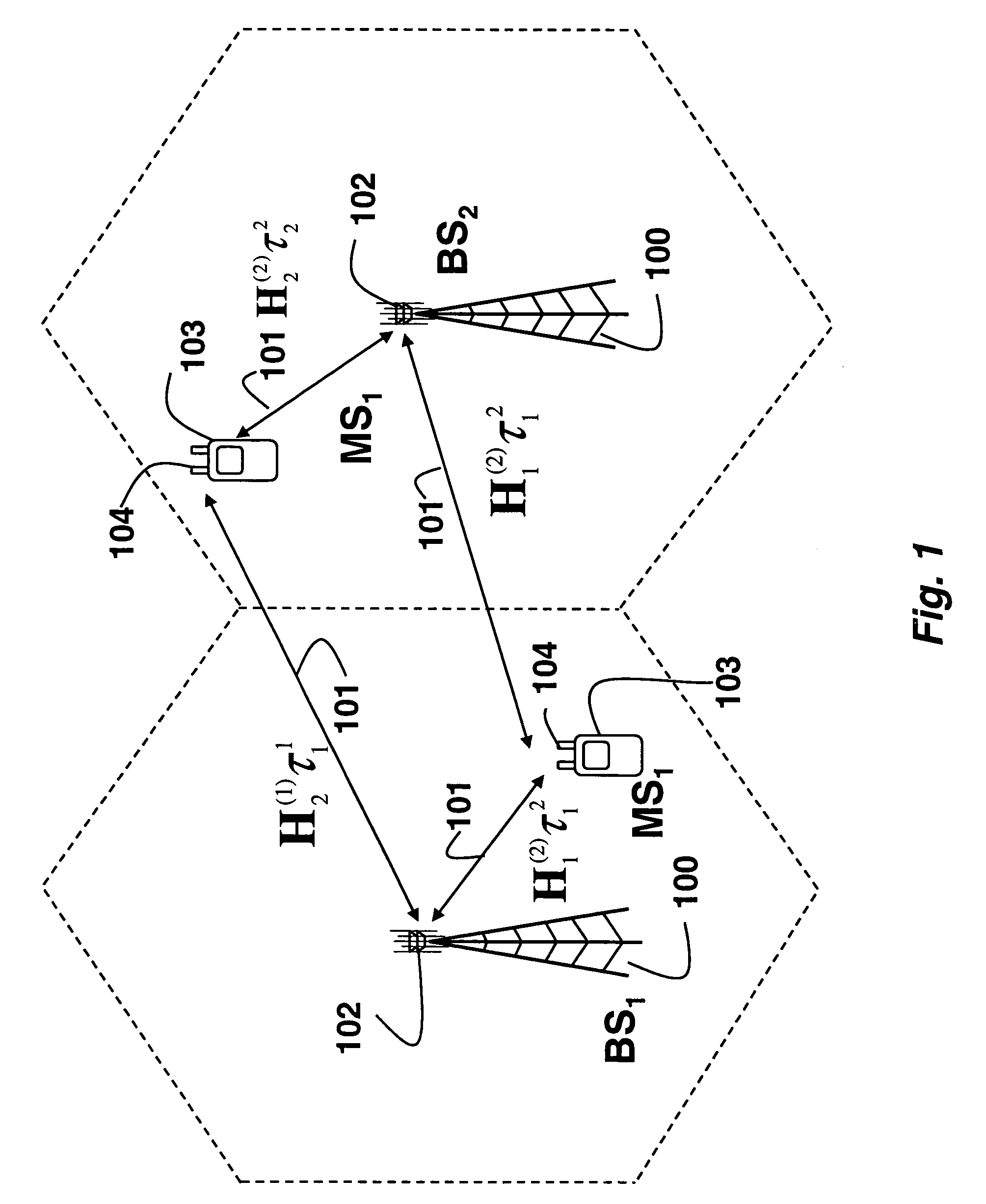
[0024]FIG. 1 shows a cooperative base station, multi-user, multi-input, multi-output network according to an embodiment of our invention. The network includes B base stations (BSs) 100. Each BS has NT antennas 102, where T is greater than one. The base stations transmit signals 101 in a cooperative manner. There are also K mobile stations (MSs) 103. Each MS has NR antennas 104, where R is one or more. For example, the base station is located at a cellular site, and the mobile stations (users) are cellular transceivers (‘cell phones’). Each station can transmit or receive radio signals. The signals from the BSs partially overlap as shown in FIG. 1. That is, both MS1 and MS2 can receive signals from both BS1 and BS2.

[0025] The basic idea behind the invention is that signals transmitted by multiple base stations to a particular mobile station are synchronous with respect to each other, and asynchronous with respect to signals transmitted by...


PUM


Abstract

A method transmits and receives signals in a cooperative, multi-user, multi-input, multi-output network. The network includes base stations (BSs) and mobile stations (MSs). Each BS has at least two antennas, and each MS has at least one antenna. At a first base station and a second base station using linear pre-coding matrices, a plurality of data streams are jointly pre-coded to produce first signals and second signals. The first signals are transmitted synchronously from the first BS and the second BS to a first MS, and the second signals are transmitted synchronously from the first BS and the second BS to a second MS, and in the first signal and the second signal are asynchronous with respect each other.

Description

FIELD OF THE INVENTION [0001] This invention relates generally to multi-input, multi-output (MIMO) communication networks, and more particularly to transmitting signals to reduce inter-cell interference in cooperative base station, multi-user MIMO networks. BACKGROUND OF THE INVENTION [0002] Spectral efficiency gains in multi-input, multi-output (MIMO) communication networks are significant for point-to-point links. However, the gains are limited in multi-user (transceiver) cellular networks. This is especially so in a downlink from a base station to a transceiver (mobile telephone) of a cellular network, which is also called a vector broadcast channel. [0003] In conventional cellular networks, inter-cell, co-channel interference (CCI) is primarily handled by careful radio resource management techniques such as power control, frequency reuse, and assignments of spreading codes. [0004] In recent years, a number of more advanced techniques that outperform conventional approaches have ...

Claims


Application Information

Patent Timeline
IPC IPC(8): H04K1/10
CPCH04B7/024
Inventor MEHTA, NEELESH B.ZHANG, HONGYUANMOLISCH, ANDREAS F.ZHANG, JINYUN
Owner MITSUBISHI ELECTRIC RES LAB INC
Why Eureka
Try Eureka