
Apparatus for High-Throughput Electroporation

Active Publication Date: 2007-10-25
BIO RAD LAB INC
View PDF6 Cites 65 Cited by
  • Summary
  • Abstract
  • Description
  • Claims
  • Application Information

AI Technical Summary

Benefits of technology

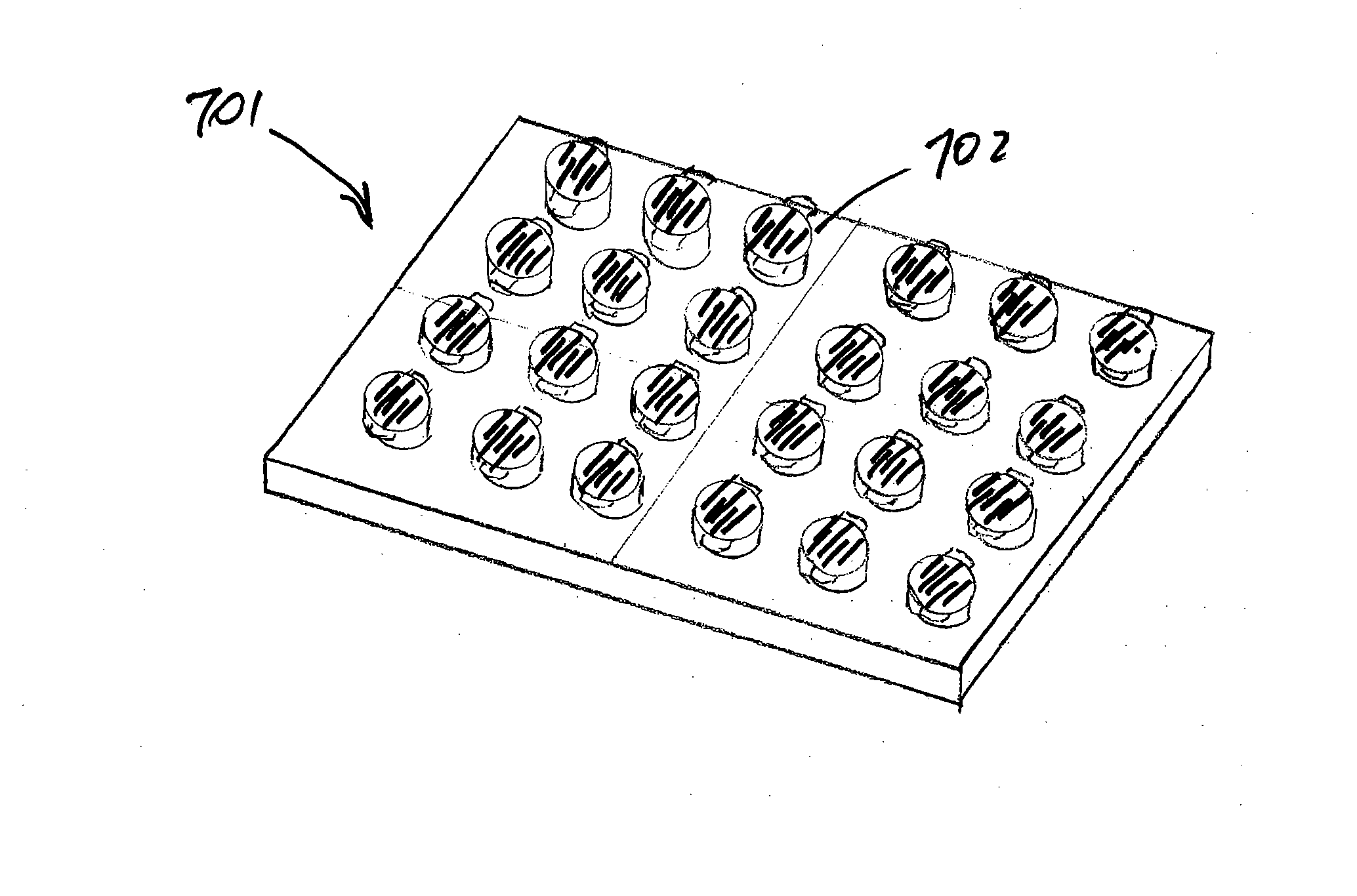
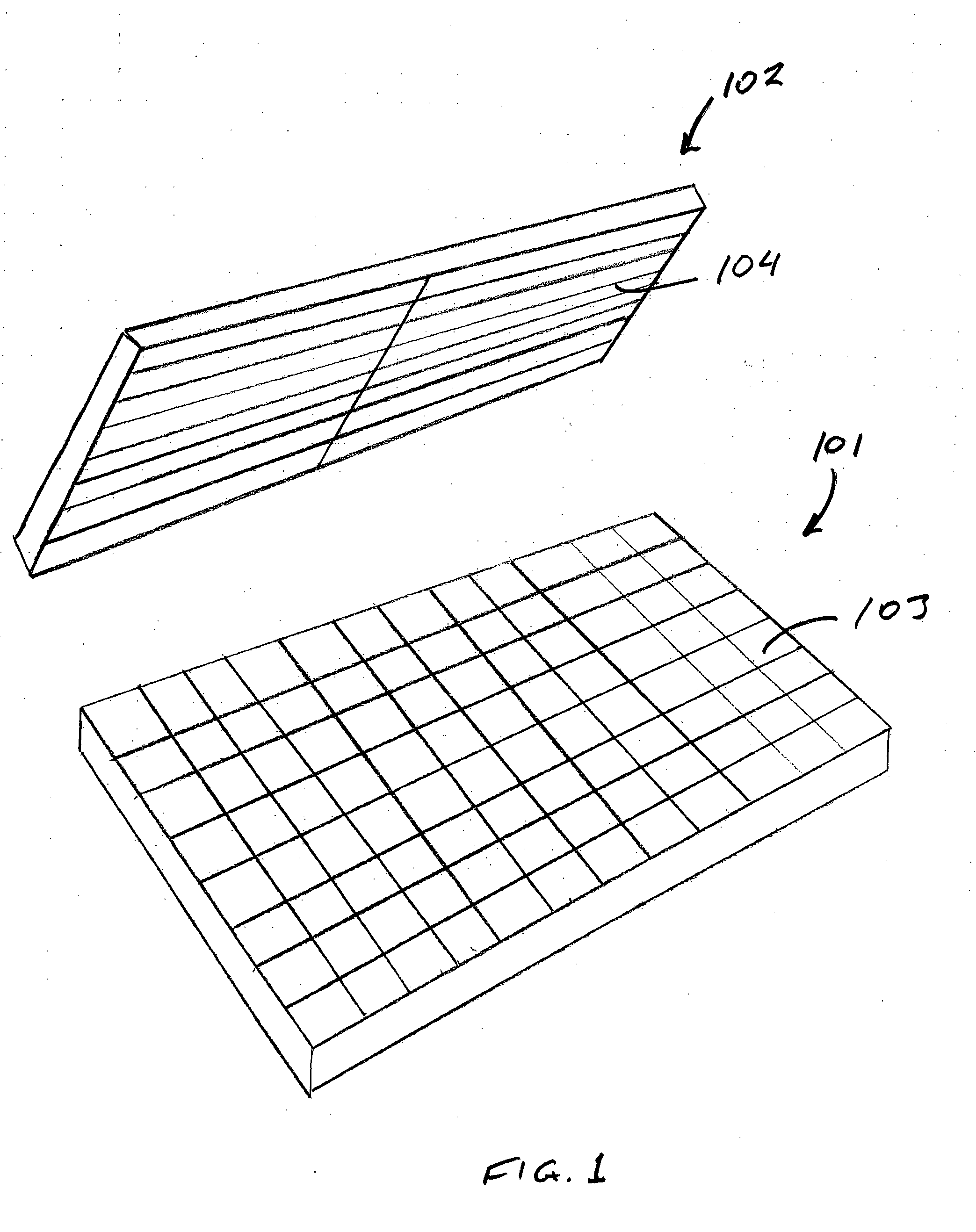
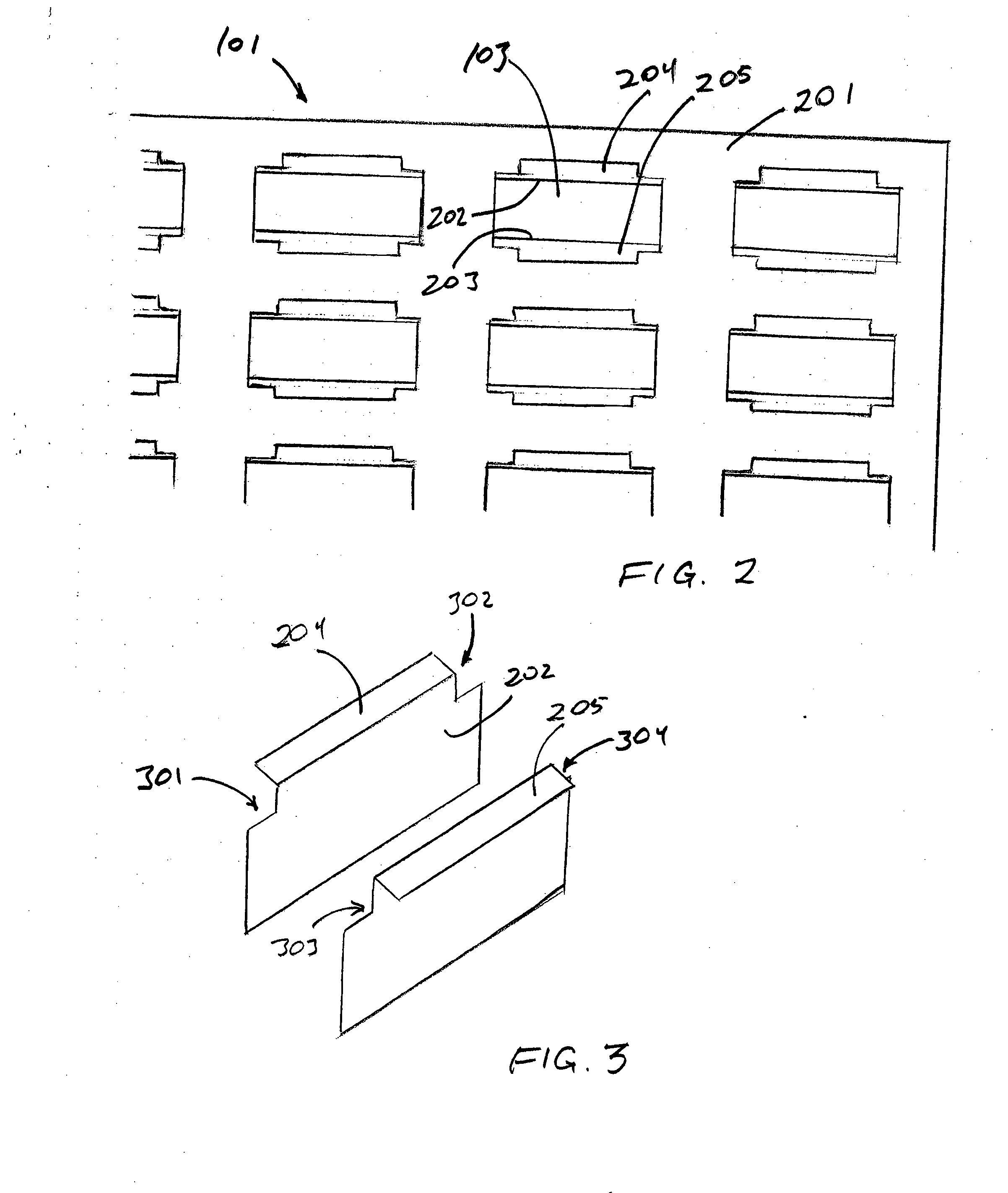
[0008] The present invention resides in electroporation plates that are an improvement over the prior art due to their ability to form electrical connections to a power supply by simple contact with electrical leads in a lid rather than in the plate itself or in a substrate supporting the plate. While the electrodes are in the interiors of the wells, either as linings on the walls of the wells or as plates or baffles immersed in the interior volumes of the wells, the connections with electrical leads in the lid are achieved by extensions of the electrodes to areas outside the wells. In certain embodiments, these extensions are lateral contact areas such as pads, shoulders, or platforms on the upper rim or edge or each well, while in other embodiments, these extensions are upper edges of the electrodes that protrude vertically above the wells. In all cases, the extensions are exposed for contact with opposing leads on the underside of the lid that are joined to a power source through electrical connections within the lid. In one group of embodiments, the electrodes in the well interiors are plated areas on opposing walls of the well, while in another group, the electrodes are baffles protruding from the well walls into the interior space of the well. Three or more baffles, although preferably four or five, are used in preferred embodiments, with alternating baffles connected to different polarities, i.e., odd numbered baffles connected for a negatively-charged polarity and even-numbered baffles for a positively-charged polarity. In a still further group of embodiments, the electrodes are thin plates spanning the entire width of the well. Three or more such plates are preferred, and most preferred are an even number such as four or more. In the case of thin plates with vertical upward extensions, the lid preferably contains individual contacts for each plate. When the electrodes are baffles whose lengths are less t

Problems solved by technology

In general, however, electroporators are limited by their resistance to electrical energy.
This limits the use of the wells and deprives the electroporator of versatility.

Method used


Image

  • Apparatus for High-Throughput Electroporation
  • Apparatus for High-Throughput Electroporation
  • Apparatus for High-Throughput Electroporation

Examples


Embodiment Construction

[0023] The term “a” or “an” is intended to mean “one or more.” The term “comprise” and variations thereof such as “comprises” and “comprising,” when preceding the recitation of a step or an element, are intended to mean that the addition of further steps or elements is optional and not excluded. All patents, patent applications, and other published reference materials cited in this specification are hereby incorporated herein by reference in their entirety. Any discrepancy between any reference material cited herein and an explicit teaching of this specification is intended to be resolved in favor of the teaching in this specification. This includes any discrepancy between an art-understood definition of a word or phrase and a definition explicitly provided in this specification of the same word or phrase.

[0024] While the features defining this invention are capable of implementation in a variety of constructions, the invention as a whole will be best understood by a detailed exami...


PUM


Abstract

An electroporator for high-throughput electroporation is constructed with a well plate in which each well has internal electrodes that extend beyond the opening of the well to form contact areas, either as horizontal platforms extending laterally from the well rims or as extended heights of thin electrode plates. The electroporator also includes a lid that contains circuitry and electrical contacts that mate with the exposed contact areas in the well plate. The interchangeability of lids allows the wells to be shocked according to different protocols.

Description

CROSS-REFERENCE TO RELATED APPLICATION [0001] This application claims the benefit of U.S. Provisional Patent Application No. 60 / 771,994, filed Feb. 10, 2006, the contents of which are incorporated herein by reference in their entirety.BACKGROUND OF THE INVENTION [0002] 1. Field of the Invention [0003] This invention resides in the field of electroporation, a process for inserting exogenous molecular species into membranous structures by suspending the structures is a liquid solution of the exogenous species and applying an electric field to the suspension. In particular, this invention concerns apparatus used for high-throughput electroporation, which term is defined as electroporation performed a multitude of cell suspensions either simultaneously or in rapid succession. [0004] 2. Description of the Prior Art [0005] Electroporation is a technique that involves the use of an electric field to impregnate membranous structures such as living biological cells, liposomes, and vesicles w...

Claims


Application Information

Patent Timeline
IPC IPC(8): C12M1/42
CPCC12M35/02C12M23/12
Inventor RAGSDALE, CHARLES W.FULLER, JOHN M.STEPHENS, NICHOLAS R.
Owner BIO RAD LAB INC
Learn More