
Channel binding mechanism based on parameter binding in key derivation

a channel binding and parameter technology, applied in the field of channel binding parameters, can solve the problems of mutual authentication, inability to assume that routing protocols support any eap method-specific code, and inability to deliver packets properly

Active Publication Date: 2007-10-25
TELCORDIA TECHNOLOGIES INC +2
View PDF5 Cites 76 Cited by
  • Summary
  • Abstract
  • Description
  • Claims
  • Application Information

AI Technical Summary

Benefits of technology

The present invention provides a method for authenticating a mobile supplicant to an access network using a channel binding key derived from a key binding master key and a key binding blob. This method improves upon previous authentication methods by not requiring the parameters to be carried in the authentication process. The method also allows for the creation of multiple channel binding keys from a single key binding master key for multiple authenticators. The key derivation function used in the method is computed based on CBK=kdf+(CBMK, KBB). The authenticator can be an EAP authenticator, which receives and processes the channel binding key as a Master Session Key (MSK). The technical effects of this invention include improved security and efficiency in authentication processes.

Problems solved by technology

Otherwise, routing protocols would not be able to deliver the packets properly.
In fact, since a pass-through authenticator is not required to implement any EAP methods at all, it cannot be assumed to support any EAP method-specific code.” Id.
For example, the [RFC3748] mandatory-to-implement EAP method (MD5-Challenge) does not provide dictionary attack resistance, mutual authentication or key derivation, and as a result is not appropriate for use in wireless LAN authentication [RFC4017].
“Since the ciphersuites used to protect data depend on the lower layer, requiring EAP methods have knowledge of lower layer ciphersuites would compromise the principle of Media Independence.
Where the peer and authenticator identify themselves within the lower layer using a port identifier such as a link layer address, this creates a problem, because it may not be obvious to the peer which authenticator ports are associated with which authenticators.
As a result, the peer and authenticator may not be able to determine the scope of the EAP keying material.
This is particularly problematic for lower layers where key caching is supported.” Id.
“For example, where the EAP peer cannot identify the EAP authenticator, it will be unable to determine whether EAP keying material has been shared outside of its authorized scope, and therefore needs to be considered compromised.
There is also a practical problem because the EAP peer will be unable to utilize the EAP authenticator key cache in an efficient way.
“When a single physical authenticator advertises itself as multiple “virtual authenticators”, the EAP peer and authenticator also may not be able to agree on the scope of the EAP keying material, creating a security vulnerability.
This ensures that an attacker cannot obtain elevated privileges even where the key cache is shared between “virtual authenticators”.
While EAP methods may derive keying material, EAP does not provide for the management of exported or derived keys.
For example, EAP does not support negotiation of the key lifetime of exported or derived keys, nor does it support re-key.
Although EAP methods may support “fast reconnect” as defined in [RFC3748] Section 7.2.1, re-key of exported keys cannot occur without re-authentication.
When an EAP re-authentication takes place, new keying material is derived and exported by the EAP method, which eventually results in replacement of calculated keys, including the TSKs.

Method used


Image

  • Channel binding mechanism based on parameter binding in key derivation
  • Channel binding mechanism based on parameter binding in key derivation
  • Channel binding mechanism based on parameter binding in key derivation

Examples


Embodiment Construction

[0098] While the present invention may be embodied in many different forms, a number of illustrative embodiments are described herein with the understanding that the present disclosure is to be considered as providing examples of the principles of the invention and that such examples are not intended to limit the invention to preferred embodiments described herein and / or illustrated herein.

[0099] Illustrative Architecture

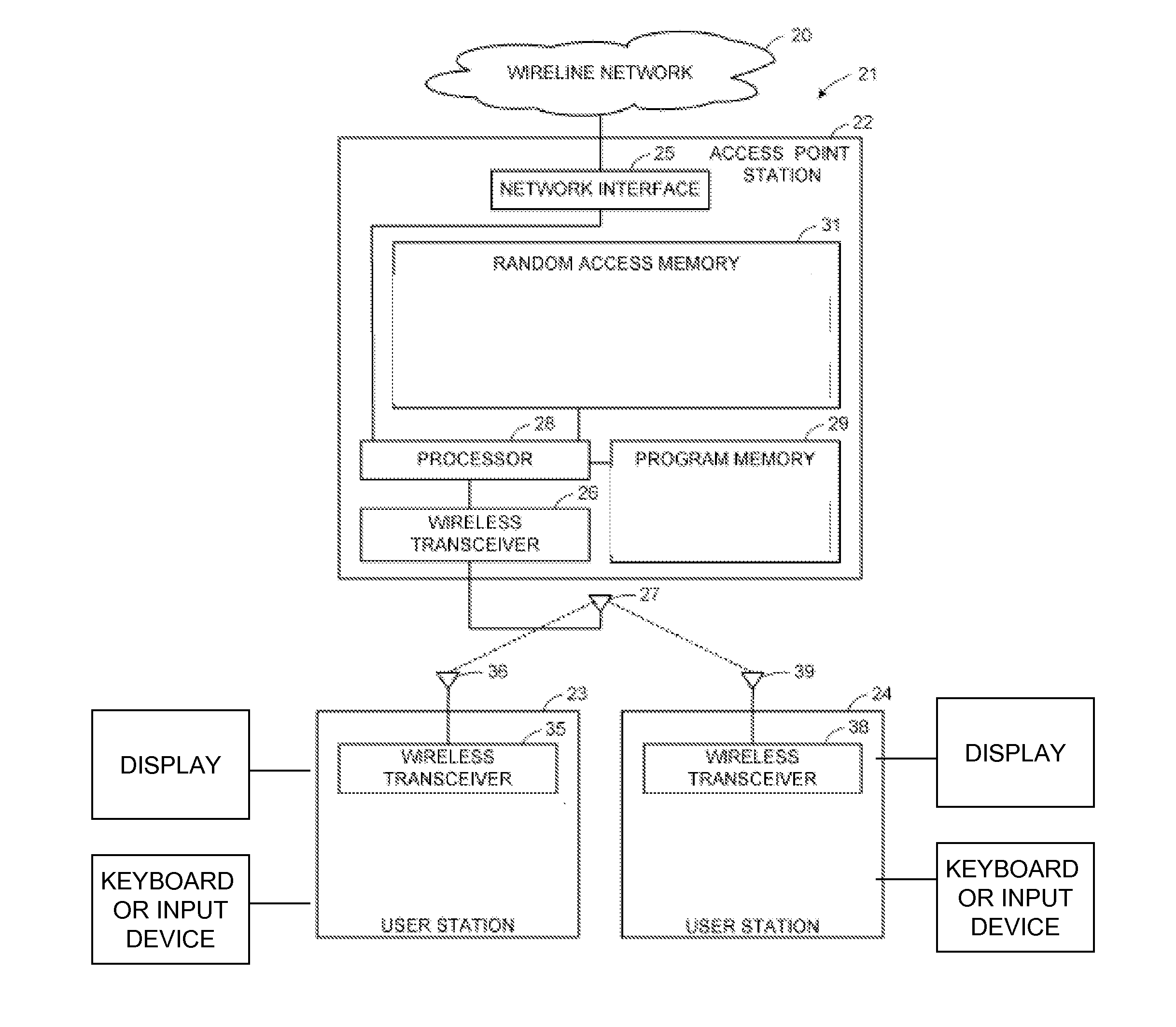
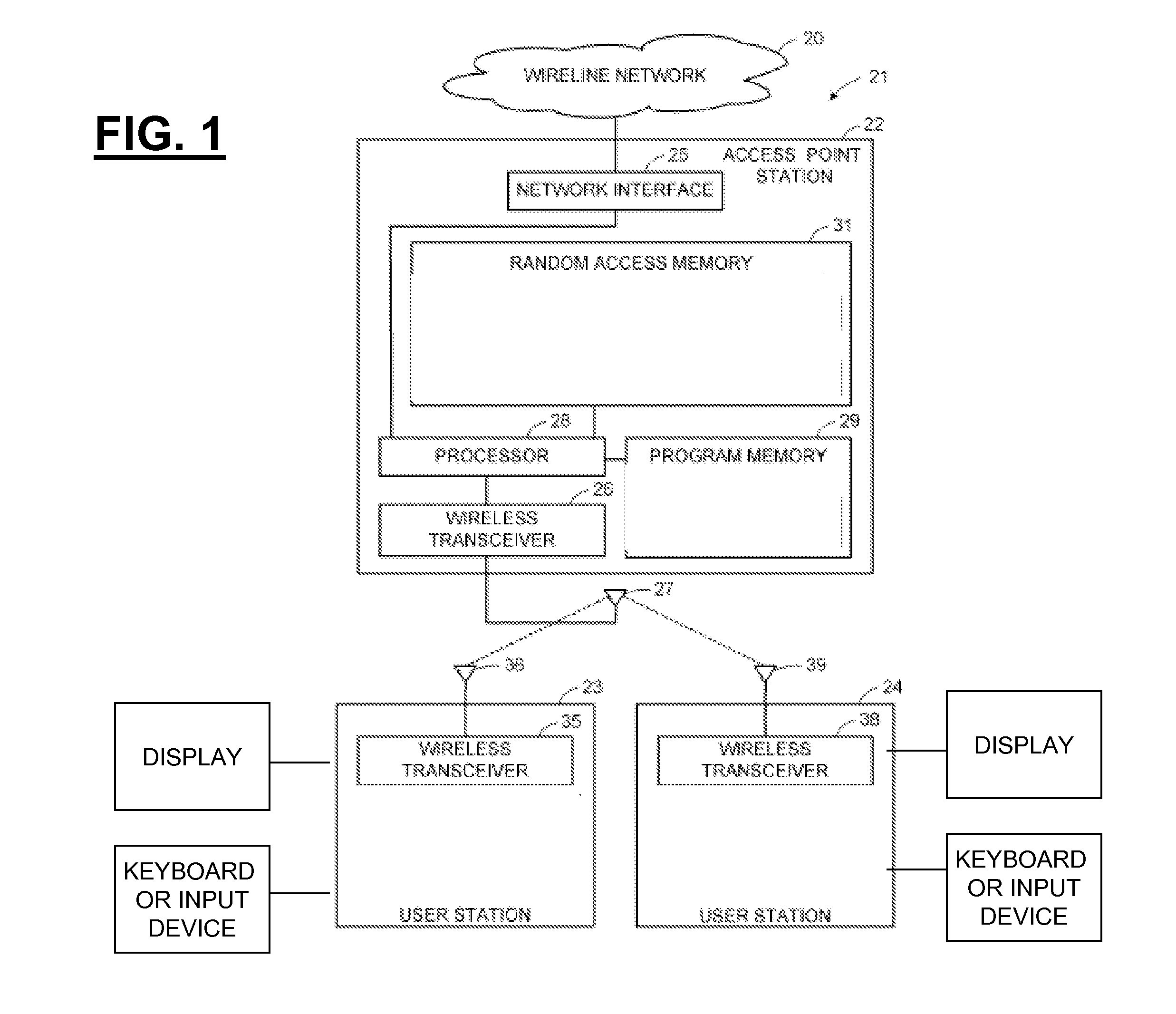
[0100]FIG. 1 depicts some illustrative architectural components that can be employed in some illustrative and non-limiting implementations including wireless access points to which client devices communicate. In this regard, FIG. 1 shows an illustrative wireline network 20 connected to a wireless local area network (WLAN) generally designated 21. The WLAN 21 includes an access point (AP) 22 and a number of user stations 23, 24. For example, the wireline network 20 can include the Internet or a corporate data processing network. For example, the access point 22 can...


PUM


Abstract

This document describes a channel binding mechanism based on parameter binding in the key derivation procedure. The method cryptographically binds access network parameters to a key without need to carry those parameters in EAP methods.

Description

BACKGROUND [0001] 1. Field of the Invention [0002] The present application relates to wireless communications and in particular to, inter alia, a methods and systems for channel binding parameters that are verified for consistency between a peer and a server. [0003] 2. Background Discussion [0004] Networks and Internet Protocol: [0005] There are many types of computer networks, with the Internet having the most notoriety. The Internet is a worldwide network of computer networks. Today, the Internet is a public and self-sustaining network that is available to many millions of users. The Internet uses a set of communication protocols called TCP / IP (i.e., Transmission Control Protocol / Internet Protocol) to connect hosts. The Internet has a communications infrastructure known as the Internet backbone. Access to the Internet backbone is largely controlled by Internet Service Providers (ISPs) that resell access to corporations and individuals. [0006] With respect to IP (Internet Protocol)...

Claims


Application Information

Patent Timeline
Patent Type & Authority Applications(United States)
IPC IPC(8): H04L9/00
CPCH04L63/06H04L63/0823H04L63/162H04L9/3273H04L9/321H04L2209/80H04L9/0838H04L2463/081
Inventor OBA, YOSHIHIRO
Owner TELCORDIA TECHNOLOGIES INC
Learn More