
Methods and apparatus for fabricating blades

a blade and blade shell technology, applied in the field of blades, can solve the problems of time-consuming and/or difficult to form parts of the rotor blade shell,

Inactive Publication Date: 2007-11-01
GENERAL ELECTRIC CO
View PDF21 Cites 105 Cited by
  • Summary
  • Abstract
  • Description
  • Claims
  • Application Information

AI Technical Summary

Problems solved by technology

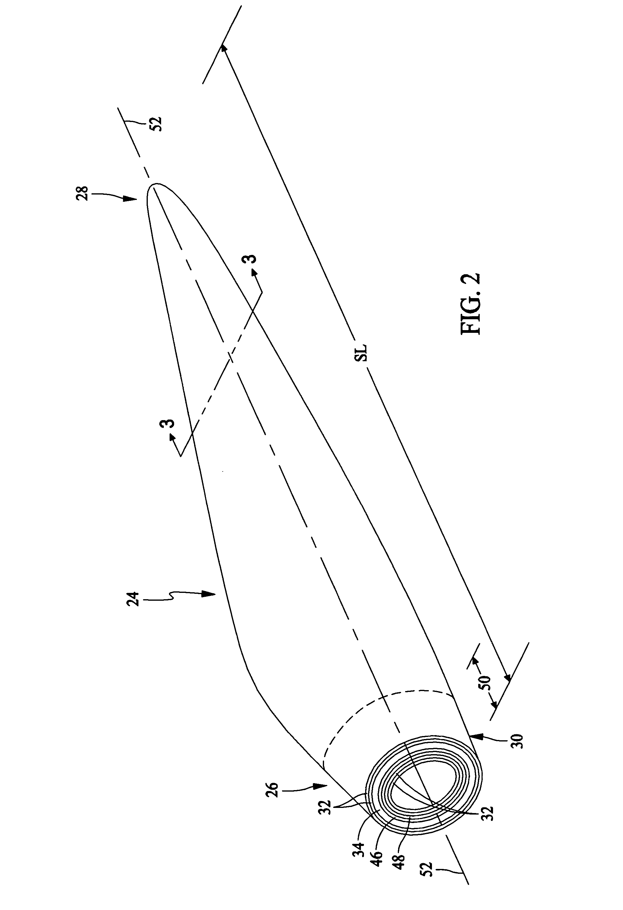
However, it may be difficult and / or time-consuming to form some components of rotor blade shells, for example spar caps, core material, and / or root section supports, such that they will both sufficiently support the rotor blade shell and be formed into the predetermined aerodynamic shape, for example because of a size of the layers, local variations in resin content, local variations in a curvature of the layers, and / or local variations in strains exerted on the shell during fabrication thereof.

Method used


Image

  • Methods and apparatus for fabricating blades
  • Methods and apparatus for fabricating blades
  • Methods and apparatus for fabricating blades

Examples


Embodiment Construction

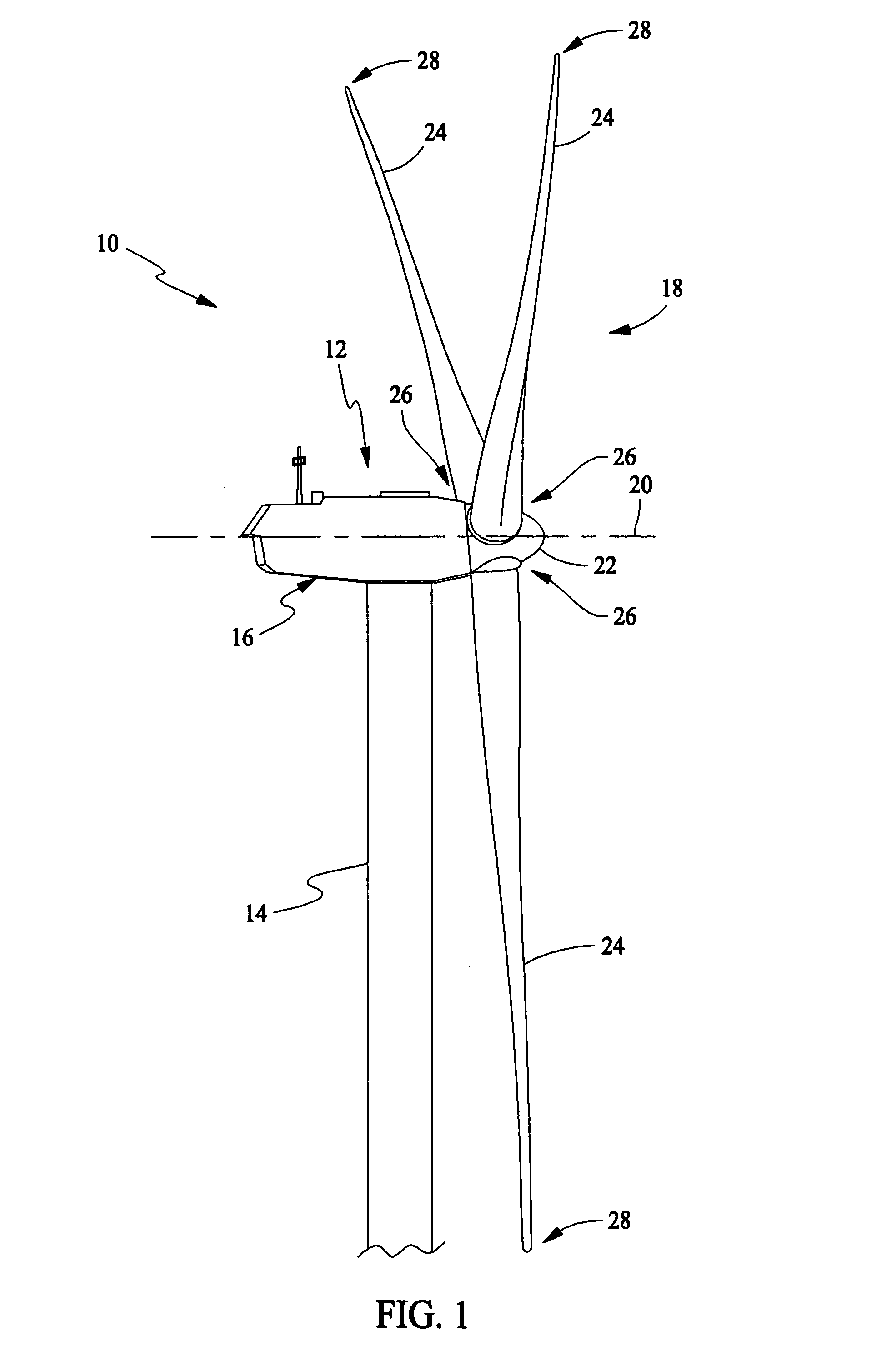
[0013] As used herein, the term “blade” is intended to be representative of any device that provides reactive force when in motion relative to a surrounding fluid. As used herein, the term “wind turbine” is intended to be representative of any device that generates rotational energy from wind energy, and more specifically, converts kinetic energy of wind into mechanical energy. As used herein, the term “wind generator” is intended to be representative of any wind turbine that generates electrical power from rotational energy generated from wind energy, and more specifically, converts mechanical energy converted from kinetic energy of wind to electrical power. As used herein, the term “windmill” is intended to be representative of any wind turbine that uses rotational energy generated from wind energy, and more specifically mechanical energy converted from kinetic energy of wind, for a predetermined purpose other than generating electrical power, such as, but not limited to, pumping ...


PUM

PropertyMeasurementUnit
lengthsaaaaaaaaaa
lengthsaaaaaaaaaa
lengthsaaaaaaaaaa

Abstract

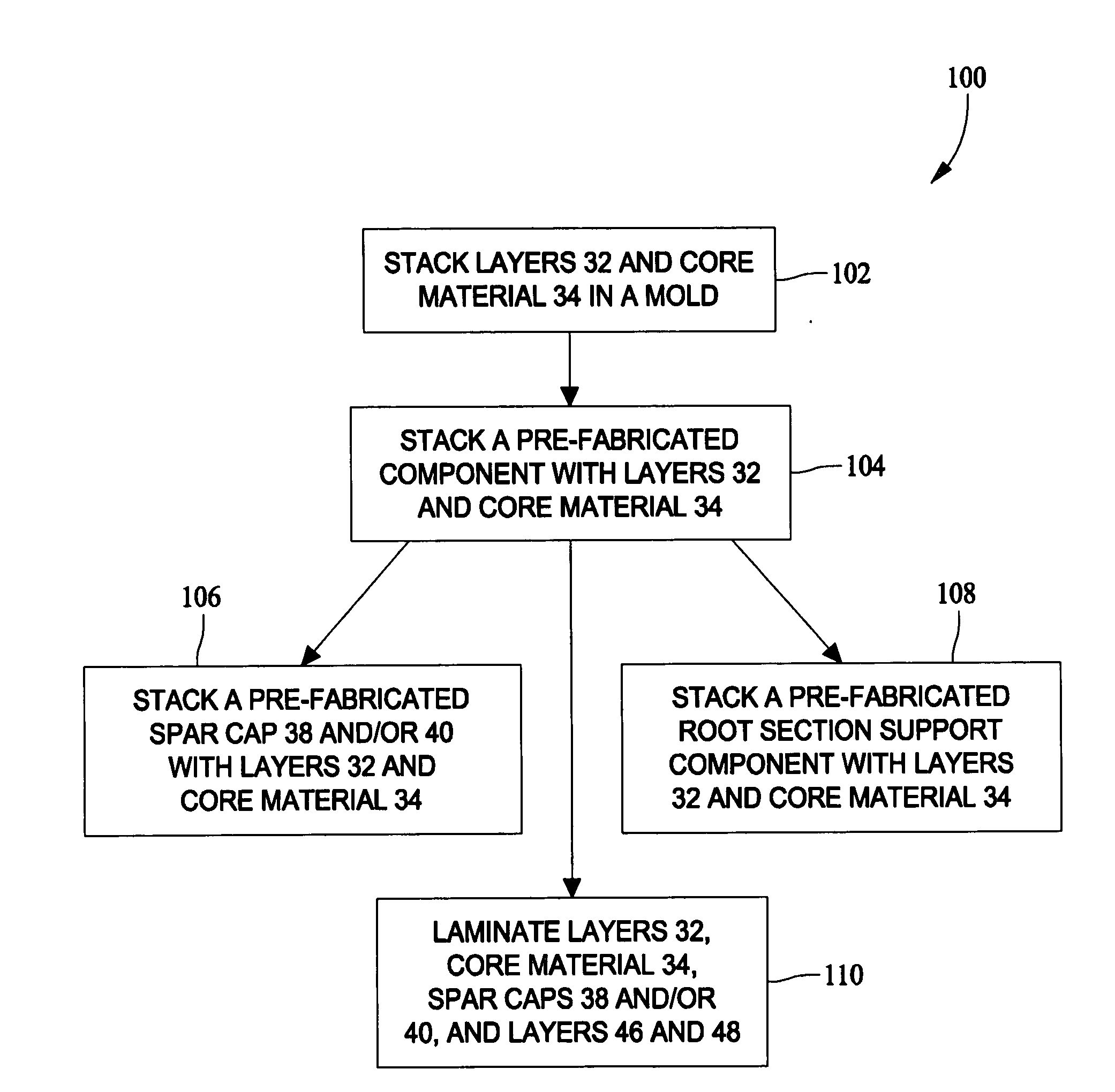
A method for fabricating a blade using a mold having a shape corresponding to a predetermined finished shape of at least a portion of the blade. The method includes stacking a plurality of layers of a material in the mold, stacking at least one component with the stack of the plurality of layers, wherein the component is a composite comprising a cured resin and at least one layer of fiber, and laminating the stack of the plurality of layers and the component.

Description

BACKGROUND OF THE INVENTION [0001] This invention relates generally to blades that may be useful as wind turbine rotor blades, and more specifically to methods and apparatus for fabricating to blades. [0002] Generally, a wind turbine includes a rotor having multiple blades. The rotor is mounted on a housing or nacelle, which is positioned on top of a truss or tubular tower. Utility grade wind turbines (i.e., wind turbines designed to provide electrical power to a utility grid) can have large rotors (e.g., 30 or more meters in diameter). Blades on these rotors transform wind energy into a rotational torque or force that drives one or more generators, generally but not always rotationally coupled to the rotor through a gearbox. The gearbox steps up the inherently low rotational speed of the turbine rotor for the generator to efficiently convert mechanical energy to electrical energy, which is fed into a utility grid. Gearless direct drive turbines also exist. [0003] At least some know...

Claims


Application Information

Patent Timeline
Patent Type & Authority Applications(United States)
IPC IPC(8): B23P15/02
CPCB29C70/30B29C70/865B29L2031/08B29L2031/085B32B5/26Y10T29/49336F03D1/0675F05B2280/6003F05C2253/04Y02E10/721B32B2603/00B32B27/04Y02E10/72Y02P70/50
Inventor BREUGEL, SJEF VANBAKHUIS, JAN WILLEMBILLEN, ANDY JOHN
Owner GENERAL ELECTRIC CO
Learn More