Tire provided with a sensor placed between the carcass ply and the inner liner

a technology of strain sensor and inner liner, which is applied in the direction of tyre measurement, vehicle components, transportation and packaging, etc., can solve the problem of affecting the air tightness of the tyr

Inactive Publication Date: 2007-11-01
MICHELIN RECH & TECH SA
View PDF3 Cites 15 Cited by
  • Summary
  • Abstract
  • Description
  • Claims
  • Application Information

AI Technical Summary

Benefits of technology

[0022] Another embodiment of the invention consists in orienting the sensor diaphragm in such a way as to make it parallel to ...

Problems solved by technology

The person skilled in the art would avoid placing a sensor in the immediate vicinity of the inner liner because any damage done to ...

Method used


Image

  • Tire provided with a sensor placed between the carcass ply and the inner liner
  • Tire provided with a sensor placed between the carcass ply and the inner liner
  • Tire provided with a sensor placed between the carcass ply and the inner liner

Examples


Embodiment Construction

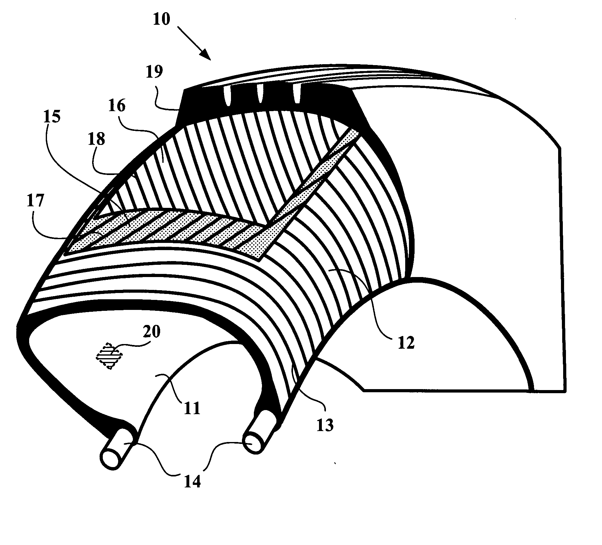
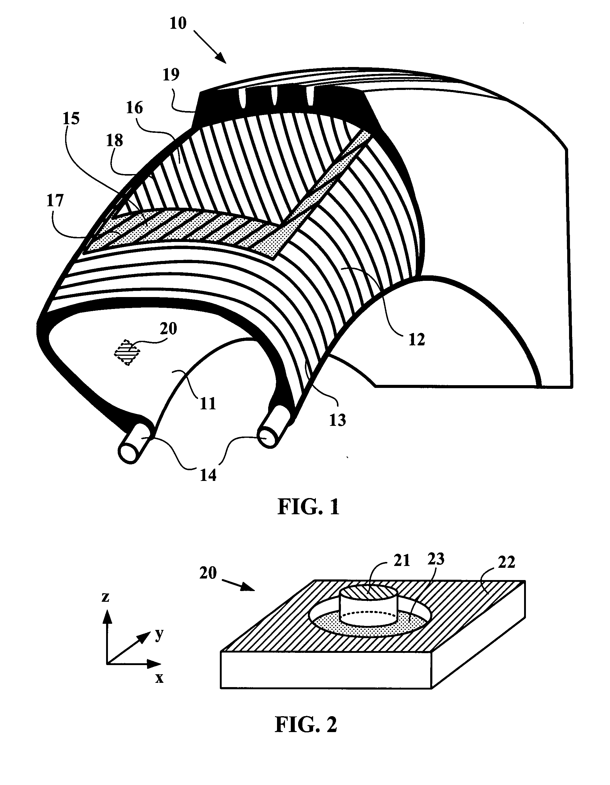
[0035]FIG. 1 is a schematic representation of a conventional tire 10, comprising an inner liner 11 of impermeable rubber, a carcass ply 12 consisting of threads 13 coated in rubber mix (that is to say rubber composition comprising at least one elastomer and a filler), circumferential reinforcements 14 which hold the tire 10 on the rim (not shown) and a crown reinforcement comprising two plies 15, 16. Each of the plies 15 and 16 is reinforced by cords 17 and 18, which are inclined relative to a plane perpendicular to the axis of rotation of the tire. A tread 19 is placed on the plies 15 and 16; it is this tread 19 which ensures contact between the tire 10 and the road. The tire is fitted with a sensor 20 which is placed between the inner liner 11 and the carcass ply 12 and whose structure is illustrated in the following Figures. The sensor 20 is shown by dotted lines, because it is covered by the inner liner 11.

[0036]FIG. 2 is a schematic representation of a three-dimensional strain...


PUM


Abstract

Tire comprising an inner liner, at least one carcass ply and a strain sensor, the strain sensor being placed between the carcass ply and the inner liner.

Description

RELATED APPLICATIONS [0001] This application claims priority from U.S. Provisional Patent Application Ser. 60 / 800,921 filed May 16, 2006 and French application no. 06 / 02805 filed Mar. 30, 2006.BACKGROUND OF THE INVENTION [0002] 1. Field of the Invention [0003] The present invention relates to tires provided with strain sensors and more particularly to the positioning of strain sensors in the structure of a tire. [0004] 2. Technical background [0005] The assistance and monitoring systems present in vehicles are constantly being developed, with the objective of increasing comfort, performance and safety. Consequently, new needs are arising for the measurement of different parameters. Some of these parameters may be determined using sensors provided in the tires. In particular, variables associated with the stress to which the tires are exposed (tire deflection, tensor of forces at wheel centre, proximity of grip limit etc.) may be obtained by measuring deformation and strain in the ti...

Claims


Application Information

Patent Timeline
IPC IPC(8): B60C19/08
CPCB60C23/064B60C19/00
Inventor BERTRAND, DAVID
Owner MICHELIN RECH & TECH SA
Why Eureka
Try Eureka