
Access control system with RFID and biometric facial recognition

a technology of facial recognition and access control system, which is applied in the field of access control badges, can solve the problems of not allowing for the exploitation of proper system integration, relying on a large number of people, and it is almost impossible to have a human be responsible for catching all of the exceptions

Inactive Publication Date: 2007-11-01
KAIL KEVIN J +2
View PDF21 Cites 155 Cited by
  • Summary
  • Abstract
  • Description
  • Claims
  • Application Information

AI Technical Summary

Benefits of technology

[0019] The present invention employs UHF RFID technology, combined with biometric recognition to provide the basis for the access control systems. The invention integrates RFID data from an ID badge with bi...

Problems solved by technology

For high security access points, the traditional security pillars of CCTV, intercom and access control have historically coexisted as components of a fragmented system, using primarily analog signals, with only crude interfaces that do not allow for the exploitation of proper system integration.
The weakness in access control systems today is that most of them rely on a human to catch and subsequently process exceptional conditions such as tailgating (multiple people walking through a secured location at the same time using only one ID badge to open the door) and buddy badging (having one person log two badges in the system when only one person enters the zone).
Given human nature and the repetitive nature of access control systems, it is almost impossible to have a human be responsible for catching all of the exceptional cases.
Yet, these systems are still far from perfect.

Method used


Image

  • Access control system with RFID and biometric facial recognition
  • Access control system with RFID and biometric facial recognition
  • Access control system with RFID and biometric facial recognition

Examples


Embodiment Construction

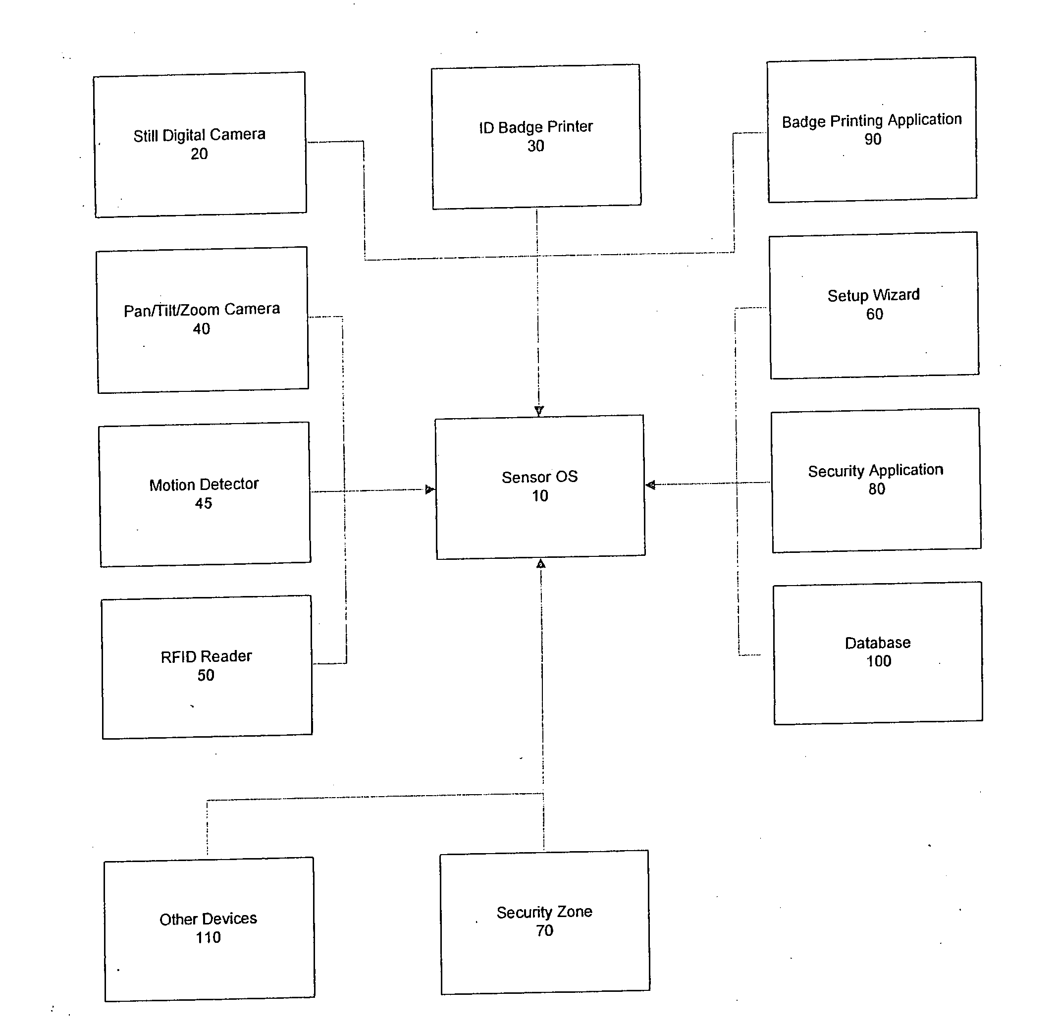
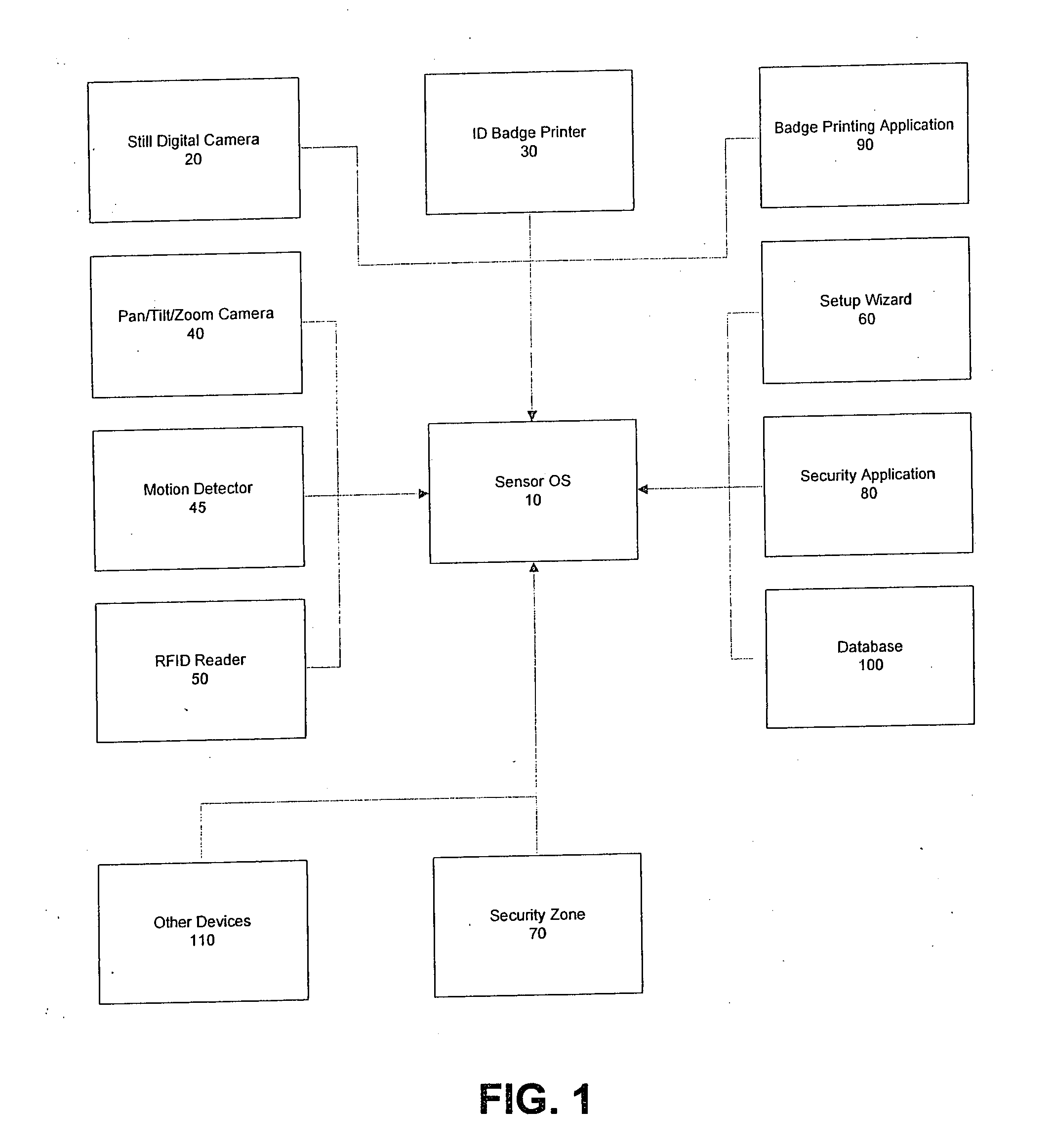
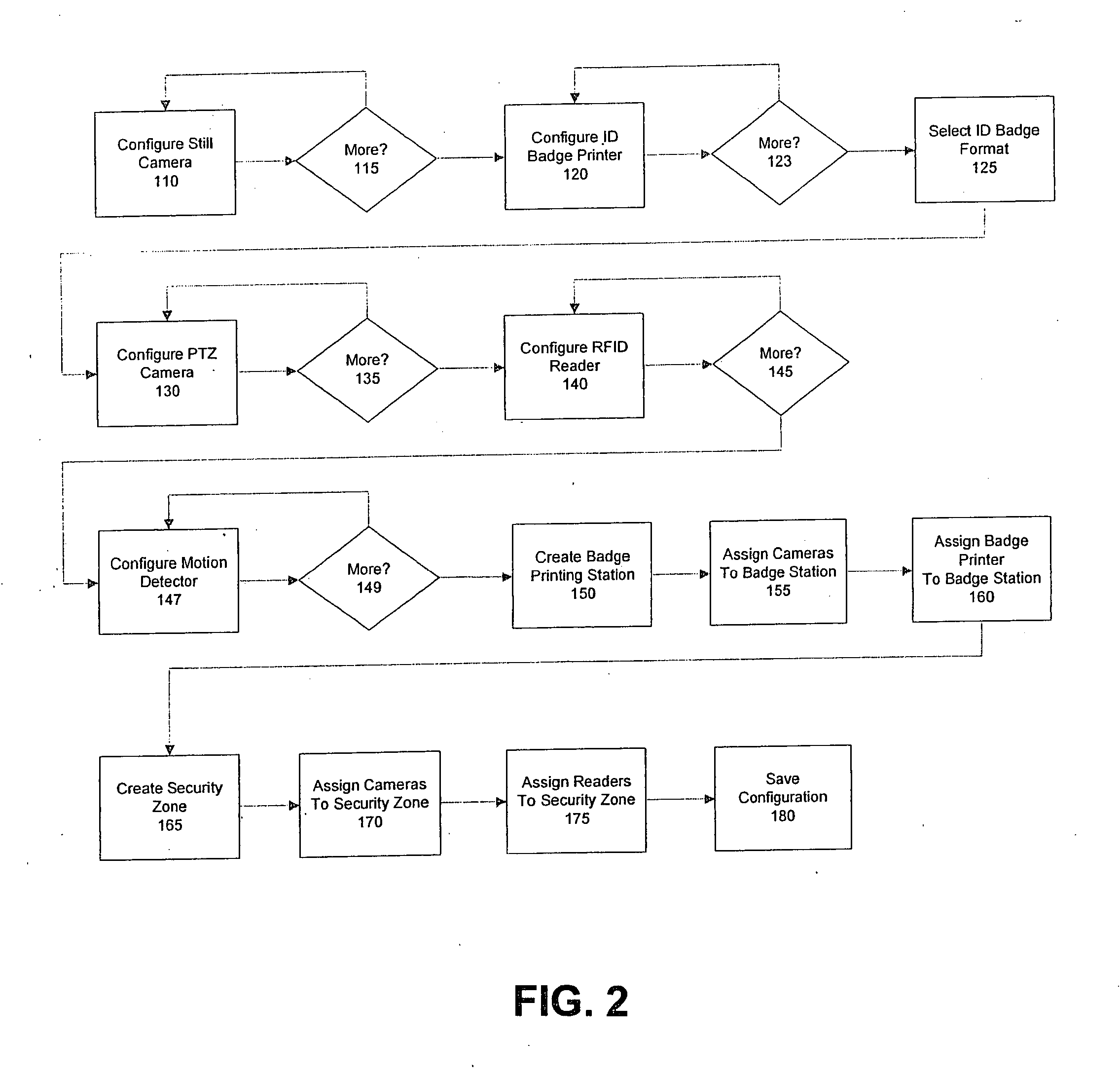
[0028] The preferred embodiment and best mode of the invention is shown in FIGS. 1 through 4. While the invention is described in connection with certain preferred embodiments, it is not intended that the present invention be so limited. On the contrary, it is intended to cover all alternatives, modifications, and equivalent arrangements as may be included within the spirit and scope of the invention as defined by the appended claims.

[0029] Documents of value such as passports, identification cards, entry passes, ownership certificates, financial instruments, and the like, are often assigned to a particular person by personalization data. Personalization data, often present as printed images, can include photographs, signatures, personal alphanumeric information, and barcodes, and allows human or electronic verification that the person presenting the document for inspection is the person to whom the document is assigned. Many countries have plans to include radio-frequency identifi...


PUM


Abstract

A biometric identification system which uses a UHF radio frequency identification (RFID) tag storing a first set of specified biometric information on an identity card; which bears a facial picture of the card carrier. An identification system comprising an antenna using radio frequency signals and a reader is used to read the first set of specified biometric information from the tag when the identify card is within sensing range of the identification system. A camera captures and digitalizes the facial features of the card carrier when the card carrier approaches a designated area and transmits this digital data to a computer which compares the first set of specified biometric information obtained by the reader from the identity card and the second set of digital facial information obtained from the camera to the stored biometric information to determine if the two sets of biometric information are a match.

Description

RELATED APPLICATIONS [0001] There are no related applications. STATEMENT REGARDING FEDERALLY SPONSORED RESEARCH OR DEVELOPMENT [0002] Not applicable. REFERENCE TO SEOUENCE LISTING, A TABLE OR A COMPUTER PROGRAM LISTING COMPACT DISC APPENDIX [0003] None. FIELD OF TIE INVENTION [0004] The present invention generally relates to access control badges with RFID tags embedded in them matched to biometric information of the person carrying the badge. BACKGROUND OF THE INVENTION [0005] A door with a latching mechanism was initially used to control access to a room or building and later security was provided by a lock and key mechanism. Security progressed with electromechanical devices which provided the ability to gain access to a building via a door / entry point, by pressing a button / switch, and completing the circuit, which activated the electric motor to disengage the latching mechanism controlling the door. [0006] Card readers were introduced in the early 1930's and used punch cards. In...

Claims


Application Information

Patent Timeline
IPC IPC(8): G06K5/00
CPCG07C9/00142G07C9/00087G07C9/257G07C9/33
Inventor KAIL, KEVIN J.WILLIAMS, CHARLES B.KAIL, RICHARD L.
Owner KAIL KEVIN J
Learn More