Non-uniformity energy correction method and apparatus

a technology of non-uniformity and energy correction, applied in the field of nuclear medicine devices, can solve the problems of inaccuracy in camera imaging, linearity error, or spatial distortion, energy non-uniformity across the face of the crystal, etc., and achieve the effect of maximizing optimal linearity and uniformity characteristics

Active Publication Date: 2007-11-01
SIEMENS MEDICAL SOLUTIONS USA INC
View PDF6 Cites 7 Cited by
  • Summary
  • Abstract
  • Description
  • Claims
  • Application Information

AI Technical Summary

Benefits of technology

[0010] Embodiments of the current invention decouple geometric and energy correction to maximize optimal linearity and uniformity characteristics of a nuclear medicine imaging apparatus. Advancements in computing power, such as the recently developed Foresight hardware, enable more sophisticated algorithms in real time computation than have been previously allowed. Such newly available computational abilities enable new methodologies and systems for correcting distortions.

Problems solved by technology

However, inaccuracies are introduced into the camera imaging due to the manufacturing process as well as the physical characteristics of the detecting apparatus.
The major distortions are linearity errors, or spatial distortion, and energy non-uniformity across the face of the crystal.
Spatial distortion generally arises from the fact that the geometric coordinates of light events occurring either at the edges of or between adjacent photomultiplier tubes in a photodetector array will be computed differently than the coordinates of events occurring directly over the center of a photomultiplier tube, due to the physical limitations of the photomultiplier tube.
Addressing non-uniformity during manufacture would not be practicable and would drive up cost.
During scanning of a radiation source, there may be emissions or scattered events from unwanted sources, which if recorded can negatively affect the precision of the resulting image.
However, due to non-uniformities across the scintillation crystal, emissions with appropriate energy may appear to fall outside the energy window and so will not be recorded by the apparatus, thereby introducing image deterioration.
Often, as uniformity is improved, the linearity distortion increases as well.
Current methods do not adequately address the relationship between energy correction and linearity correction.
If uniformity is corrected before linearity correction, uniformity correction cannot be achieved in totality.

Method used


Image

  • Non-uniformity energy correction method and apparatus
  • Non-uniformity energy correction method and apparatus
  • Non-uniformity energy correction method and apparatus

Examples


Embodiment Construction

[0024] While the present invention may be embodied in many different forms, a number of illustrative embodiments are described herein with the understanding that the present disclosure is to be considered as providing examples of the principles of the invention and such examples are not intended to limit the invention to preferred embodiments described herein and / or illustrated herein.

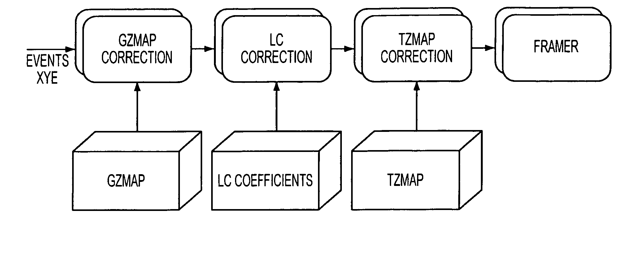
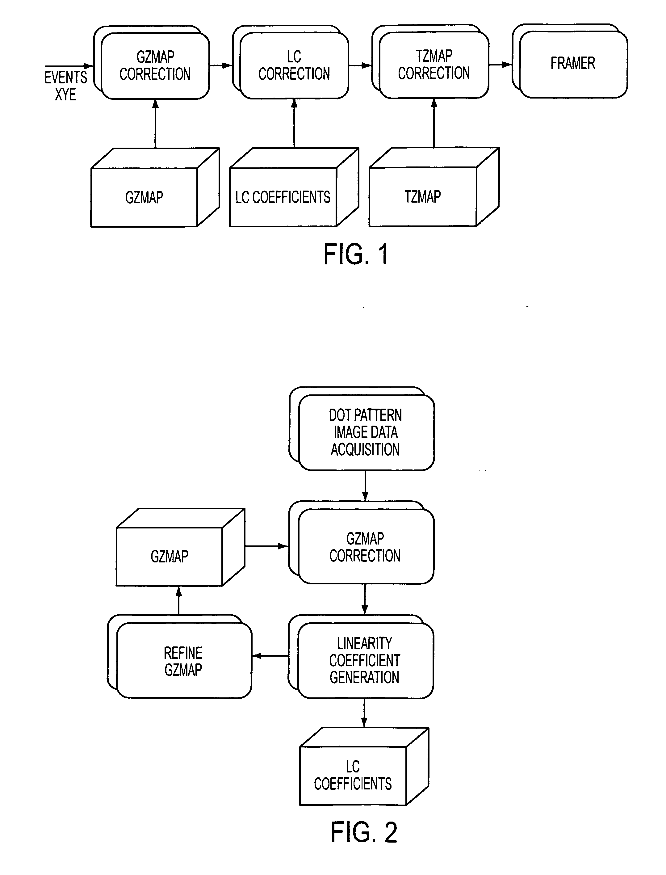
[0025] One embodiment of an overall process according to the present invention is shown in FIG. 1. As shown, the major corrective steps involved in the invention begin with applying to individual event data (comprising X, Y spatial coordinates and Z energy signal) a generic energy map correction (GZmap) to normalize the Z signal for each event, followed by a linearity correction (LC) using linearity correction coefficients to correct spatial distortion errors, which is followed by a Twin Zmap correction (TZmap), to calibrate total uniformity, wherein the event is then ready for framing.

[0026] One cal...


PUM


Abstract

A method and apparatus for acquiring total uniformity for a scintillation imaging apparatus are provided. A generic energy (Z) map is first obtained. The generic Zmap is then corrected for linearity by use of a dot pattern. The listmode data is used to construct an energy histogram matrix. A twin Zmap is then obtained by optimizing the lower and upper boundaries of the energy window for each pixel in relation to the average energy over the Center Field of View.

Description

BACKGROUND OF THE INVENTION [0001] 1. Field of the Invention [0002] The present invention generally relates to nuclear medicine devices, in particular the calibration of scintillation cameras to correct for non-uniformities in energy distribution as a function of position across the camera field of view. [0003] 2. Description of the Background Art [0004] Nuclear medicine is a unique medical specialty wherein radiation is used to acquire images that show the function and anatomy of organs, bones or tissues of the body. Radiopharmaceuticals are introduced into the body, either by injection or ingestion, and are attracted to specific organs, bones or tissues of interest. Such radiopharmaceuticals produce gamma photon emissions that emanate from the body. One or more detectors are used to detect the emitted gamma photons, and the information collected from the detector(s) is processed to calculate the position of origin of the emitted photon from the source (i.e., the body organ or tiss...

Claims


Application Information

Patent Timeline
Patent Type & Authority Applications(United States)
IPC IPC(8): G01D18/00
CPCG01T7/005G01T1/1642
Inventor WANG, SHARON XIAORONGCARUBA, JAMES FRANKMALMIN, RONALD E.DELMEDICO, ANTHONY P.
Owner SIEMENS MEDICAL SOLUTIONS USA INC
Why Eureka
Try Eureka