Control of Electrical Machines

a technology of electrical machines and rotors, applied in the direction of electronic commutators, dynamo-electric machines, synchronous motor starters, etc., can solve the problems of large memory requirements, difficult control of rotors at such high speeds,

Inactive Publication Date: 2007-11-01
DYSON TECH LTD
View PDF74 Cites 49 Cited by
  • Summary
  • Abstract
  • Description
  • Claims
  • Application Information

AI Technical Summary

Benefits of technology

[0010] The correction factor may be transmitted to the controller by means of radio frequency signals, whic...

Problems solved by technology

However, control of the rotor at such high speeds can be problematic.
However, suc...

Method used


Image

  • Control of Electrical Machines
  • Control of Electrical Machines
  • Control of Electrical Machines

Examples


Embodiment Construction

[0022] Like reference numerals refer to like parts throughout the specification.

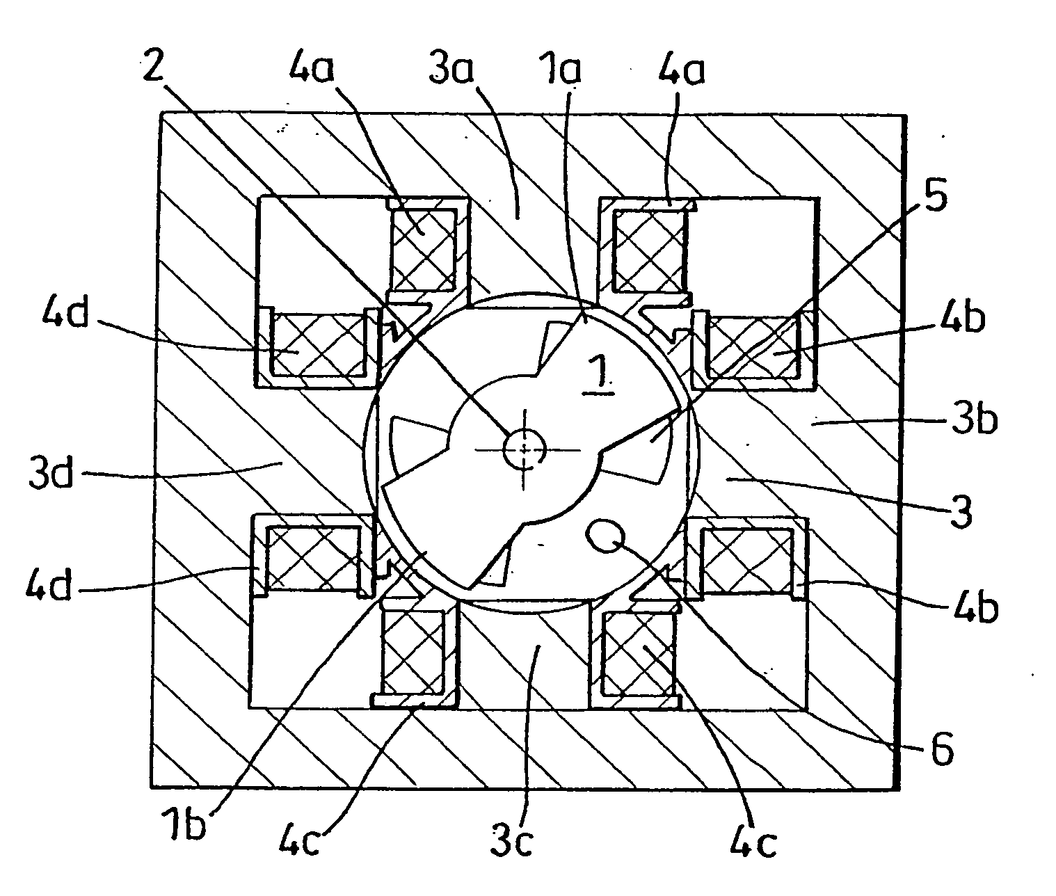
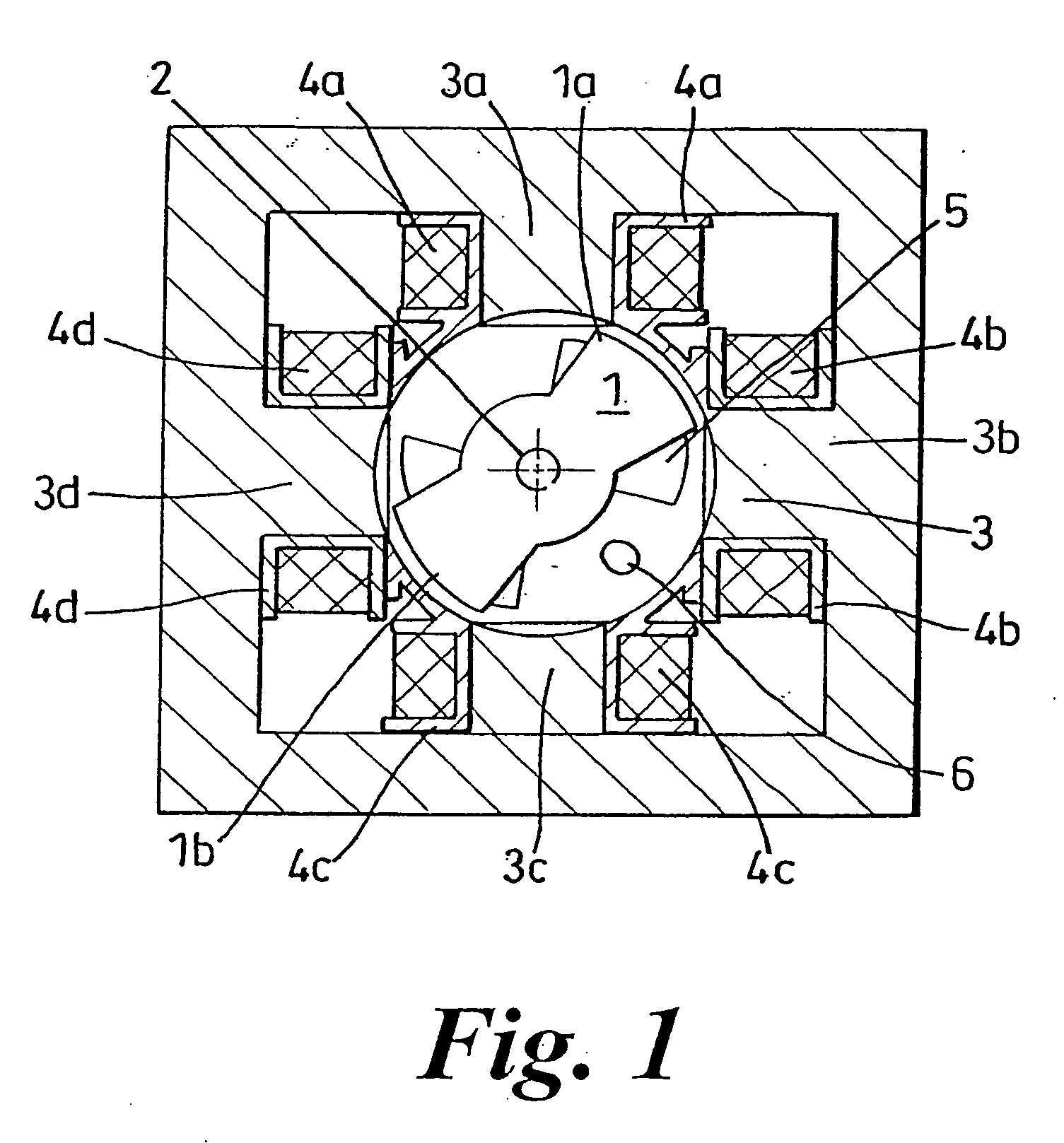
[0023]FIG. 1 is a cross-sectional view of a typical switched reluctance motor. It comprises a rotor 1, mounted on a shaft 2 and a stator 3. The rotor 1 comprises an axially laminated stack of steel plates, arranged to form a pair of poles 1a, 1b. The stator 3 comprises a stack of steel laminations arranged to have, in this example, four inwardly projecting salient poles 3a, 3b, 3c and 3d. Opposing poles 3a and 3c each support a winding 4a, 4b which together form a first phase. The other diametrically opposite poles 3b and 3d similarly accommodate respective windings 4c and 4d, which represent a second phase. Each winding 4 comprises a large number of turns (e.g. 50+ turns) of an insulated electrical conductor around the respective stator pole.

[0024] In use, energisation of the phase windings is controlled in order to effect rotation of the rotor. Thus, it is imperative that the rotational position of t...


PUM


Abstract

An electrical machine, such as a switched reluctance motor, has a rotor and at least one electrically energizable phase winding. A control map is derived during production that includes a predetermined advance angle profile representing the energization of the phase winding with respect to the angular position of the rotor over a range of rotor speeds. This is stored in memory in a controller together with an angle correction factor to be applied to a predetermined portion of the advance angle profile. The angle correction factor compensates for the difference between a desired input power and the measured input power. The correction factor may be transmitted to the controller by means of radio frequency signals.

Description

FIELD OF THE INVENTION [0001] This invention relates to controlling an electrical machine, particularly a machine of the switched reluctance type, such as a switched reluctance motor. BACKGROUND OF THE INVENTION [0002] Switched reluctance machines have become increasingly popular in recent years. In a switched reluctance motor, a stator has sets of poles that are sequentially energised to rotate a rotor into line with the energised pair of poles, under the influence of the magnetic fields associated with each set of poles. By rapidly switching between different pairs of poles, it is possible to cause the rotor to rotate at a very high speed. [0003] Recent developments in switched reluctance motors have resulted in higher speeds of rotation of the rotor than was achievable hitherto. However, control of the rotor at such high speeds can be problematic. In particular, the angular position of the rotor at which the poles are energised and de-energised needs to be controlled carefully [0...

Claims


Application Information

Patent Timeline
IPC IPC(8): H02P6/14H02P25/08
CPCH02P25/082H02P6/145H02P25/0925H02P6/153H02P25/08H02P6/14
Inventor CLOTHIER, ANDREWGREETHAM, STEPHENDAI, HANPING
Owner DYSON TECH LTD
Why Eureka
Try Eureka