
Affixing Method of Rfid Label and its Affixing Apparatus

a technology of affixing apparatus and affixing method, which is applied in the direction of burglar alarm mechanical actuation, instruments, transportation and packaging, etc., can solve the problems of high defective rate of id tag 109 and 5 to 20%, and achieve the effect of eliminating a defective id tag and reducing costs

Inactive Publication Date: 2007-11-01
IWATA LABEL CO LTD +1
View PDF10 Cites 180 Cited by
  • Summary
  • Abstract
  • Description
  • Claims
  • Application Information

AI Technical Summary

Benefits of technology

[0016] In the present invention, a display label and a ID tag are stored in a state of being separated preliminarily. Additional display is printed on the display label, whereas a test of the ID tag is conducted so as to eliminate a defective ID tag. Then, right before affixing to a product, a non-defective ID tag and the display label having the additional display printed are laminated. In this way, though additional display is printed, pressure or heat would not applied on the ID tag, so as that the ID tag would not be damaged. Also, in case of change of display information, only the display label will be discarded, and it is not necessary to discard the expensive ID tag. Further, it is necessary to apply a test of the ID tag only right before affixing to a product, and a test is not always necessary by the manufacturer of the RFID label, and therefore cost reduction can be realized.
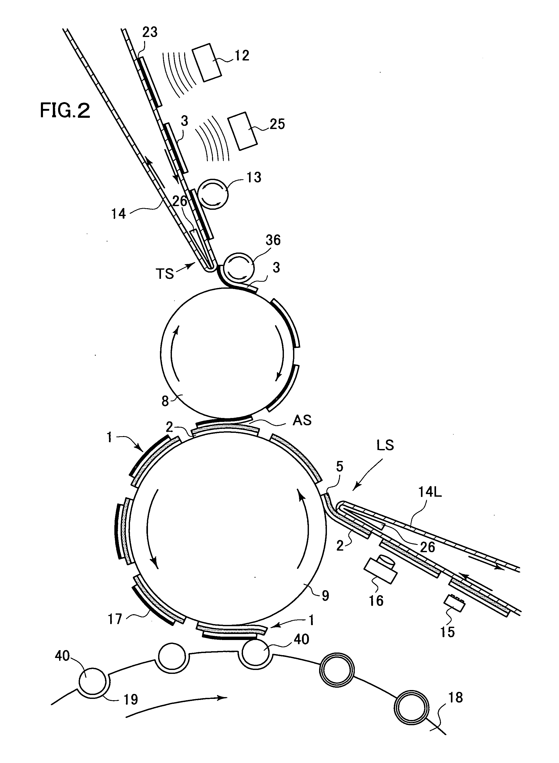
[0034] On the other hand, the present invention is provided with a writing mechanism of production information to an ID tag, and a testing mechanism to apply a reading test of the information, and a defective eliminating mechanism. By these mechanisms non-defective ID tags are selected. In case that an ID tag is supplied using a releasing member, it is preferable to dispose the writing mechanism, the testing mechanism and the defective eliminating mechanism approximately parallel with the releasing member. That is, the writing mechanism and the testing mechanism are disposed a little apart form the releasing member, so as to be capable of transmitting electric wave to and from the ID tag. This configuration allows writing, a reading test and defective elimination on the releasing member, so as to supply only a non-defective tag to the tag conveying drum.
[0040] Also, the fourth solution for the above problem is to pull out an object-to-affix having no RFID label affixed on the way of production line. An RFID label is to be affixed again to the object-to-affix pulled out. More specifically, an object-to-affix eliminating mechanism and a control device (a microcomputer or the like is used) controlling the object-to-affix eliminating mechanism and a label supplying mechanism are provided. Also, a winding up speed of the releasing member, a rotation speed of the tag conveying drum and a conveying speed of the object-to-affix are set to a constant. In case that eliminating a defective ID tag on the releasing member causes a tag absent area having no ID tag existing on a tag sticking section, in order to prevent the display label from contacting with the tag absent area, supply of the corresponding display label is stopped. That is, when the display label corresponding to the tag absent area is supplied, the control device sends a supply stop signal to the label supplying mechanism. This prevents forming of an RFID label, and causes an area having nothing stuck to (label absent area) on the label conveying drum. The label absent area contacts with an object-to-affix, resulting in that no RFID label is affixed on the object-to-affix. Therefore, it is necessary to pull out this object-to-affix on the way.
[0058] According to the above explained affixing apparatus, an ID tag and a display label are separated so as that printing additional display on the display label would not cause damage to the ID tag. Also, a test of the ID tag is not conducted right before affixing to a product, so as to realize cost reduction by omitting adjustment operations such as a testing process, elimination of a defective ID tag, re-connection of a roll or the like in an ID tag manufacturing factory.

Problems solved by technology

However in the existing circumstances there is a problem that a defective rate of the ID tag 109 is high and 5 to 20%.

Method used


Image

  • Affixing Method of Rfid Label and its Affixing Apparatus
  • Affixing Method of Rfid Label and its Affixing Apparatus
  • Affixing Method of Rfid Label and its Affixing Apparatus

Examples


Embodiment Construction

[0087] Best modes for carrying out the present invention will be explained using figures, as follows.

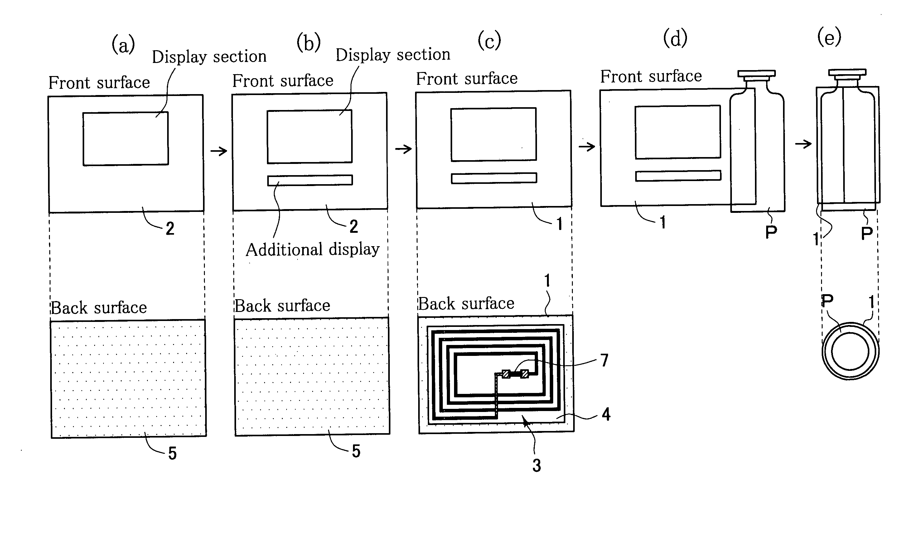
[0088] A schematic drawing of an affixing method of an RFID label relating to the present invention is shown in FIG. 1. First, as shown in FIG. 1(a),a display label 2, provided with a display section thereof but having no additional display, is prepared. On its surface information such as a product name, a manufacturer name, components or the like is printed out, and adhesive 5 is applied on its back surface as a adhesive layer to a product and an ID tag. Next, as shown in FIG. 1(b), on the surface, additional display of information such as date of manufacture, expiry date or the like is printed out. Meanwhile, not shown in a figure, on an IC chip built in an ID tag, information such as a product name, date of manufacture, a lot number or the like is written, the information is checked by applying a reading test, and then a defective ID tag, for which reading can not be applied, is ...


PUM


Abstract

A display label, having a display section on a surface thereof and an adhesive surface on a back surface thereof, and an IC tag, provided with an antenna coil and an IC chip so as to transmit information through non-contact communication, are prepared. After writing information on the IC chip, reading test is applied, so as to separate non-defective ID tags and defective ID tags. After printing addition display on the surface of the display label, a non-defective ID tag is adhered on an adhesive surface thereof, so as to form an RFID label. Then the RFID label is affixed to an object-to-affix such as a container. An affixing method of an RFID label and its affixing method are provided, wherein an ID tag is less likely to be damaged, since the ID tag is not adhered on a display label while printing additional display.

Description

RELATED APPLICATIONS [0001] This application claims the priorities of Japanese Patent Application No. 2004-156781 filed on May 26, 2004, which are incorporated herein by reference. BACKGROUND OF THE INVENTION [0002] 1. Field of the Invention [0003] The present invention relates to an affixing method of RFID label and its affixing apparatus. More specifically, it relates to a method to affix an RFID label, which is provided with an antenna coil and an IC chip and capable of transmitting information to and from an external device through non-contact communication, to an object-to-affix such as a container or the like and its affixing apparatus. [0004] 2. Description of the Related Art [0005] Conventionally bar-code has been used for stock management or sales management of a product. Recently, instead of this, use of a non-contact ID tag, which is capable of transmitting information through non-contact communication, has been increasing. This is an insulated substrate provided with an ...

Claims


Application Information

Patent Timeline
IPC IPC(8): G08B21/00B65C9/18B65C9/40B65C9/42B65C9/46G06K19/077
CPCB65C9/188B65C2009/404B65C2009/0003B65C9/42
Inventor ISHIHARA, KATSUMASAMIZUKAWA, TAKAAKI
Owner IWATA LABEL CO LTD
Learn More