
Video reproduction apparatus

a video reproduction and apparatus technology, applied in the field of video reproduction apparatus, can solve the problems of slow response of the video reproduction apparatus, degradation of the display video, and inability to perform video output utilizing the decoded image data in both the top and bottom fields, so as to prevent data from being overwritten, no distortion in image display, and no waiting time

Inactive Publication Date: 2007-11-01
PANASONIC CORP
View PDF6 Cites 2 Cited by
  • Summary
  • Abstract
  • Description
  • Claims
  • Application Information

AI Technical Summary

Benefits of technology

[0054]According to the video reproduction apparatus of the present invention, when an image is repeatedly displayed using a frame buffer having only a region less than one plane for inter-frame bidirectional predictive coded pictures, decoding is continuously performed, thereby realizing realtime repetitive reproduction and display having no distortion in image display, and requiring no waiting time.
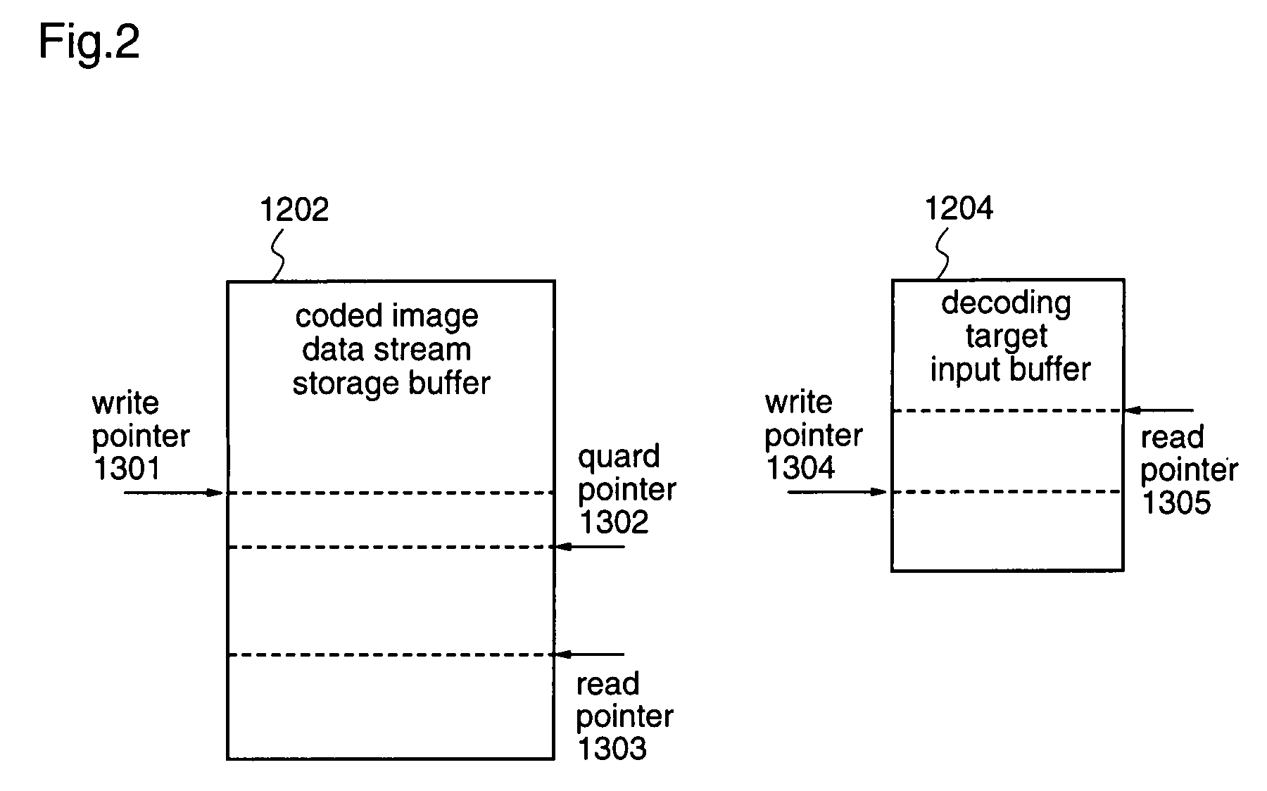
[0055]According to the first aspect of the present invention, there is provided a video reproduction apparatus for reproducing video data, including a frame buffer having a region less than one plane for storing inter-frame bidirectional predictive coded pictures, and the apparatus comprises: a header detection unit for detecting a header position of a coded image data stream that is stored in a decoding target input buffer; a decoding control unit for controlling a decoding process on the basis of header information supplied from the header detection unit, to which a reproduction instruction for performing repetitive display of the same decoded image data is inputted from the outside; a protection processing unit for calculating a position of the coded image data stream on the coded image data stream storage buffer, on the basis of the position of the coded image data stream on the decoding target input buffer, which is supplied from the decoding control unit, and protecting the position of the coded image data stream so as not to be overwritten with a coded image data stream different from the coded image data stream; and a coded image data stream transfer unit for, when there is a request from the decoding control unit for retransferring the coded image data stream, performing retransfer of the coded image data stream on the basis of the position of the coded image data stream on the decoding target input buffer. The decoding control unit notifies the coded image data stream transfer unit of the head position of the coded image data on the decoding target input buffer, which head position is detected by the header detection unit, and the protection processing unit calculates, based on the information, a position of the coded image data on the coded image data stream storage buffer, and protects the coded image data so as not to be overwritten, whereby the same coded image data can be transferred again from the coded image data stream storage buffer to the decoding target input buffer, for decoding of the data to be repeatedly displayed, thereby realizing realtime reproduction requiring repetitive display, which reproduction does not lead to deterioration in image display and does not require a waiting time until video outputting, while deterioration in image display is conventionally caused by that all data corresponding to one frame are not left in the frame buffer region, and a waiting time until video outputting is conventionally caused by that the once transferred and decoded coded data stream is again read from a disk or the like.
[0056]According to the second aspect of the present invention, in the video reproduction apparatus according to the first aspect, the protection processing unit determines as to whether the coded image data on the coded image data stream storage buffer should be protected or not, on the basis of a coding prediction direction of the coded image data. Protection for preventing data from being overwritten is not performed for non-inter-frame bidirectional predictive coded pictures to which a frame buffer region enough to store all data in one frame is allocated, and new data are stored in the coded image data stream storage buffer, thereby reducing the possibility of falling into buffer under flow which causes absence of data in the coded image data stream storage buffer.
[0057]According to the third aspect of the present invention, in the video reproduction apparatus according to the first aspect, the decoding control unit judges as to whether retransfer of the coded image data should be performed or not, on the basis of the coding prediction direction of the coded image data, and header information that is added to the coded image data or the coded image data stream. Since, when performing a reproduction processing including such as frame rate conversion for a movie material stream, coded image data for repetitive display can be obtained, realtime reproduction processing including such as frame rate conversion for a movie material stream, which does not lead to deterioration in image display and does not require a waiting time until video outputting, can be realized, while deterioration in image display is conventionally caused by that all data corresponding to one frame are not left in the frame buffer region, and a waiting time until video outputting is conventionally caused by that the once transferred and decoded coded data stream is again read from a disk or the like.
[0058]According to the fourth aspect of the present invention, in the video reproduction apparatus according to the first aspect, the decoding control unit judges as to whether retransfer of the coded image data should be performed or not, on the basis of the coding prediction direction of the coded image data, and a trick play instruction. Therefore, it is possible to obtain coded image data for repetitive display which is required when performing trick play such as pause, frame-by-frame advance, or slow motion, thereby realizing trick play such as pause, frame-by-frame advance, or slow motion having no deterioration in image display, in a video reproduction apparatus including a frame buffer having only a region less than one plane for inter-frame bidirectional predictive coded pictures.
[0059]According to the fifth aspect of the present invention, in the video reproduction apparatus according to the third or fourth aspect, even when the decoding control unit determines that retransfer of the coded image data should be performed, retransfer of the coded image data is not carried out if the size of video image to be outputted is small and decoded image data to be redisplayed remains on the frame buffer. Therefore, it is possible to finally determine as to whether retransfer of the coded image data should be performed or not, by checking the frame buffer, thereby reducing the bandwidth load when the coded image data stream storage buffer is disposed on a common memory.

Problems solved by technology

In the video reproduction apparatus 300 shown in FIG. 17 which includes a frame buffer having only a region less than one region for inter-frame bidirectional coded pictures, however, when repetitive outputting of the same inter-frame bidirectional predictive coded picture is carried out for trick play such as pause, frame-by-frame advance, slow motion, or the like, since all the decoded image data in one frame are not left in the third frame buffer region 903 for inter-frame bidirectional predictive coded pictures, it is impossible to perform video output utilizing the decoded image data in both the top and bottom fields on the frame buffer, in contrast with the conventional video reproduction apparatus 200 having the three-plane frame buffer shown in FIG. 10.
However, this method leads to degradation in the display video.
That is, it results in a slow responding video reproduction apparatus.
As described above, in the conventional video reproduction apparatus, when the region for inter-frame bidirectional coded pictures in the frame buffer is reduced for cost reduction, display image is degraded, and realtime repetitive display cannot be carried out when performing trick play.

Method used


Image

  • Video reproduction apparatus
  • Video reproduction apparatus
  • Video reproduction apparatus

Examples


embodiment 1

[0085]According to a first embodiment of the present invention, in a video reproduction apparatus 100 which reproduces video data using a frame buffer having only a region less than one plane for inter-frame bidirectional predictive coded pictures, the same coded image data can be again transferred from a coded image data stream storage buffer and displayed to realize repetitive display of inter-frame bidirectional predictive coded image data.

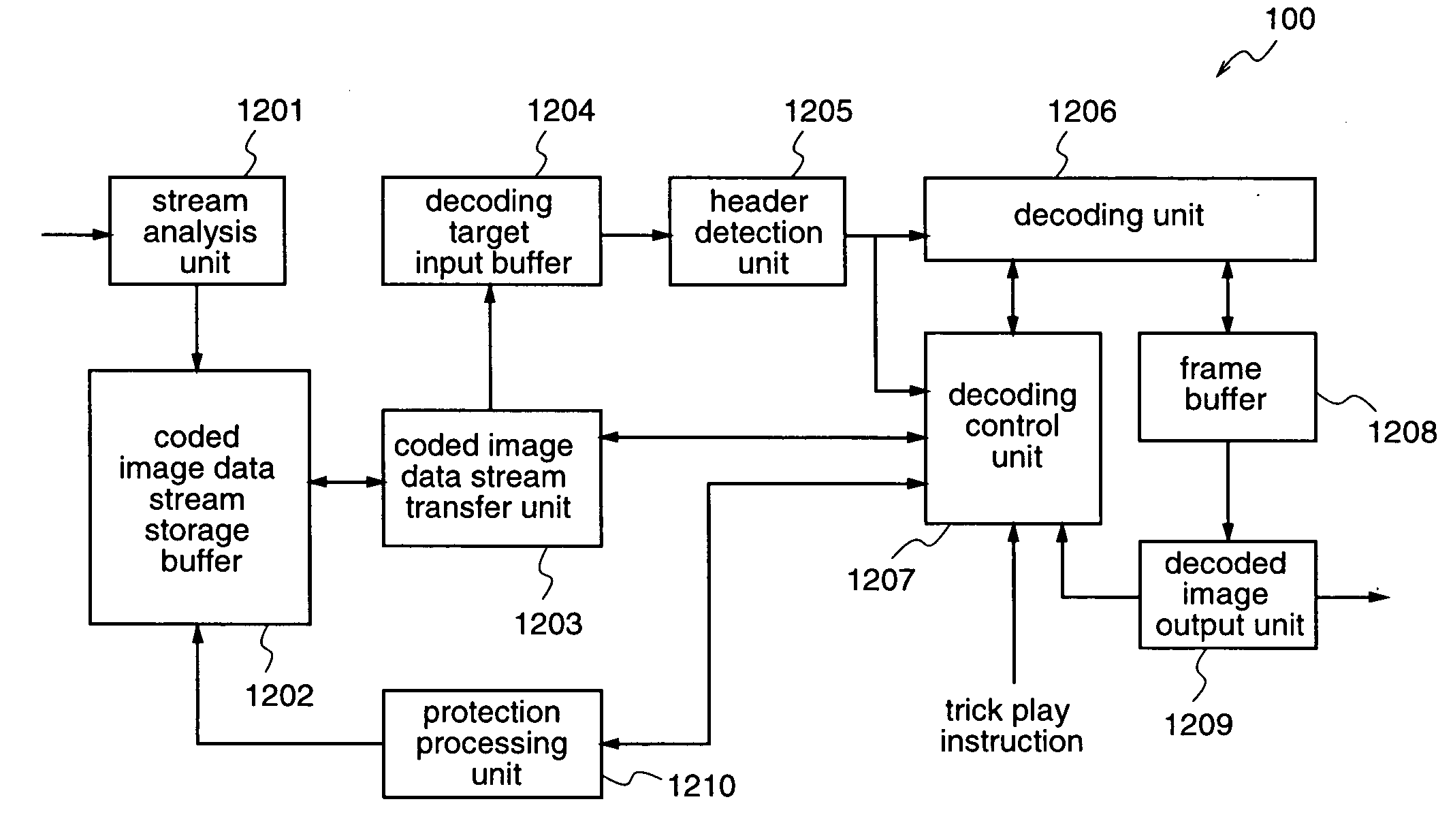
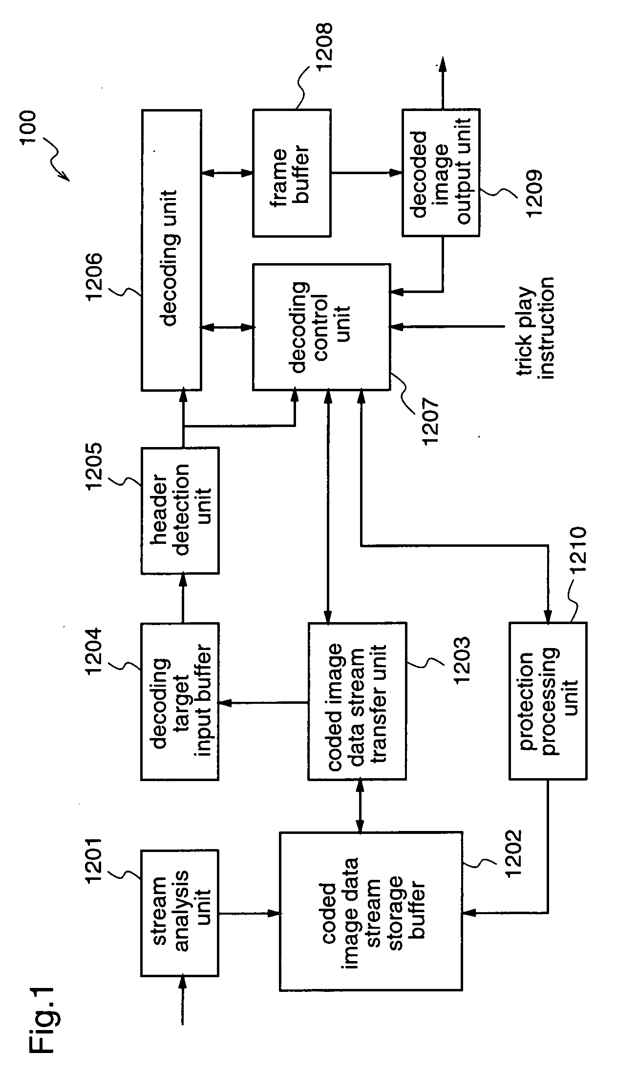
[0086]FIG. 1 is a block diagram illustrating an example of the construction of the video reproduction apparatus 100 according to the first embodiment of the present invention.

[0087]In FIG. 1, the video reproduction apparatus 100 according to the first embodiment comprises a stream analysis unit 1201, a coded image data stream storage buffer 1202, a coded image data stream transfer unit 1203, a decoding target input buffer 1204, a header detection unit 1205, a decoding unit 1206, a decoding control unit 1207, a frame buffer 1208, a decoded image...


PUM

PropertyMeasurementUnit
sizeaaaaaaaaaa
structureaaaaaaaaaa
areaaaaaaaaaaa

Abstract

A video reproduction apparatus comprises a decoding control unit 1207 for controlling a decoding process on the basis of header information, to which an instruction for repetitive display of image is inputted; a protection processing unit for calculating a position of a coded image data stream on a coded image data stream storage buffer 1202 on the basis of a position of the coded image data stream on a decoding target input buffer 1204, which position is supplied from the decoding control unit 1207, and protecting the coded image data stream so as not to be overwritten with another coded image data stream; and a coded image data stream transfer unit 1203 for performing retransfer of the coded image data stream on the basis of the position of the coded image stream on the decoding target input buffer 1204.

Description

FIELD OF THE INVENTION[0001]The present invention relates to a video reproduction apparatus and, more particularly, to a video decoding technique and a video reproduction technique to be applied to decoding and reproduction of coded video digital data which are stored in a DVD (Digital Versatile Disk), an HDD (Hard Disk Drive), or the like.BACKGROUND OF THE INVENTION[0002]There are many video reproduction apparatuses for decoding and displaying coded video data streams that have been compressed according to MPEG2 or MPEG4, which apparatuses require repetitive display of the same decoded video data. For example, movie material stream reproduction, or trick play such as pause, frame-by-frame advance, or slow motion require repetitive display of the same decoded video data.[0003]FIG. 10 is a block diagram illustrating an example of a construction of a conventional video reproduction apparatus 200 for reproducing video data based on MPEG standard.[0004]In FIG. 10, the conventional video...

Claims


Application Information

Patent Timeline
Patent Type & Authority Applications(United States)
IPC IPC(8): H03M7/00G11B20/10G11B27/10H04N5/92H04N19/423H04N19/44H04N19/50H04N19/503H04N19/577H04N19/61H04N19/625H04N19/91
CPCG11B20/10527H04N5/85G11B2020/10759G11B2020/10537
Inventor KITAGUCHI, TOMOMANABE, NORIYUKIURANO, KATSUKIKINOSHITA, SATOSHINAKAMORI, MASAHIRO
Owner PANASONIC CORP
Learn More