Signal processing arrangement for a hall sensor and signal processing method for a hall sensor

a signal processing and hall sensor technology, applied in the direction of magnetic measurements, instruments, measurement devices, etc., can solve the problems of increasing the quantization noise of the sensor interphase, limited the maximum step the loop can do each step, and invalid signal values, etc., to reduce the average power consumption, reduce the required waiting time, and reduce the effect of energy consumption

Active Publication Date: 2021-05-18
AMS AG
View PDF5 Cites 1 Cited by
  • Summary
  • Abstract
  • Description
  • Claims
  • Application Information

AI Technical Summary

Benefits of technology

[0010]An improved concept discussed below is based on the idea to compensate an offset of a Hall element directly at the signal front-end, thus taking an analog-to-digital converter, ADC, out of the equation and thereby eliminating the required waiting time. An offset compensation phase can be much quicker and the arrangement can do a wakeup-compensate-measure-power down cycle using less energy than in other solutions decreasing the average power consumption. Since in the improved concept the offset is compensated after the first phase the required startup time is substantially reduced because the first sample already is offset-free. The improved concept can be realized in a much smaller area than the current solution because existing structures of already existing cells can be adapted to form the functionality.

Problems solved by technology

Current schemes use an auto zero approach to eliminate the offset or enlarge the ADC dynamic range to cope with both signal and offset thus increasing the quantization noise of the sensor interphase.
The loop implemented by the feedback paths starts to decrease the offset based on the sampling frequency of the system but has also to maintain a stable loop therefore the maximum step the loop can do each step is limited.
Until the loop is settled the resulting signal value is not valid because the ADCs may or may not have clipped due to a too high offset value.
This fact limits the start-up time in low power applications.

Method used


Image

  • Signal processing arrangement for a hall sensor and signal processing method for a hall sensor
  • Signal processing arrangement for a hall sensor and signal processing method for a hall sensor
  • Signal processing arrangement for a hall sensor and signal processing method for a hall sensor

Examples


Embodiment Construction

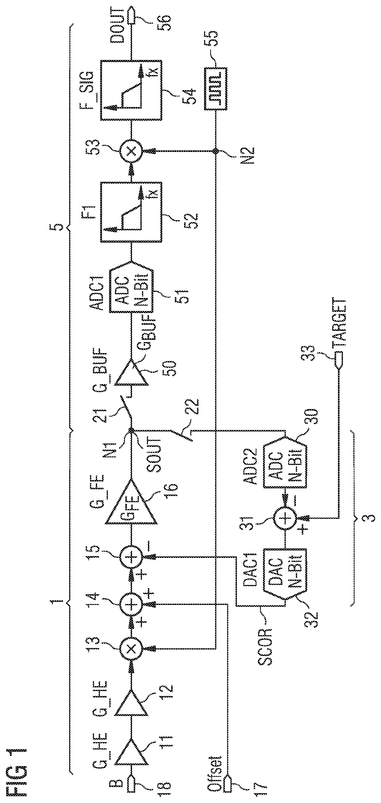
[0039]FIG. 1 shows an exemplary embodiment of a signal processing arrangement for a Hall sensor. The signal processing arrangement comprises a signal path 1, a feedback path 3 and a converter path 5.

[0040]The signal path 1 comprises a series connection with a Hall element 11, 12, a first multiplier 13, a first adder 14, a second adder 15 and a front-end amplifier 16. In the drawing the Hall element 11, 12 is represented by two consecutive amplifiers 11 and 12. The front-end amplifier 16 is coupled to the feedback path 3 and to the converter path 5 by means of a switching network. The switching network comprises a first switch 21 and a second switch 22 and are connected to a first circuit node N1. An offset terminal 17 is connected to a positive input of the first adder 14.

[0041]The feedback path 3 spans from the first circuit node N1 via the second switch 22 to the second adder 15. The second switch 22 is connected to a feedback analog-to-digital converter 30 which is connected in s...


PUM


Abstract

A signal processing arrangement for a Hall sensor comprises a signal path, a feedback path and a converter path. The signal path comprises a Hall element and a front-end amplifier which are connected in series and arranged to generate an output signal depending on a magnetic field. The feedback path comprises a compensation circuit and is coupled to the signal path. The converter path comprises an analog-to-digital converter and an offset compensation circuit and is coupled to the signal path. A switch network is coupled between the signal path, the feedback path and the converter path. In a compensation phase, the switch network electrically connects the feedback path to the signal path such that the compensation circuit generates a compensation signal which is coupled into the signal path. In a sampling phase, the switch network connects the signal path to the converter path such that the output signal is reduced by the compensation signal is provided at the converter path.

Description

CROSS-REFERENCE TO RELATED APPLICATIONS[0001]The present application is the national stage entry of International Patent Application No. PCT / EP2018 / 052428, filed on Jan. 31, 2018, which claims the benefit of priority of European Patent Application No. 17153931.5, filed on Jan. 31, 2017, all of which are hereby incorporated by reference in their entirety for all purposes.[0002]This invention relates to a signal processing arrangement for a Hall sensor and to a signal processing method for a Hall sensor.BACKGROUND OF THE INVENTION[0003]In Hall sensor applications an output signal is prone to offset of a Hall element which itself can be much larger than a desired signal the application is supposed to convert. Typically, a low noise amplifier, LNA, is also implemented and adds to the offset. Therefore the Hall sensor application usually employs offset compensation techniques to reduce this effect and make it possible to convert the output signal using an analog-to-digital converter, ADC...

Claims


Application Information

Patent Timeline
Patent Type & Authority Patents(United States)
IPC IPC(8): G01R33/00G01R33/07H03M1/12
CPCG01R33/0029G01R33/075H03M1/12H03M1/1023G01R15/202
Inventor RUCK, DOMINIKOBERHOFFNER, GERHARD
Owner AMS AG
Why Eureka
Try Eureka