
Interface

Inactive Publication Date: 2006-12-07
SHARP KK
View PDF17 Cites 14 Cited by
  • Summary
  • Abstract
  • Description
  • Claims
  • Application Information

AI Technical Summary

Benefits of technology

[0011] Because the interface of the present invention repeatedly changes and displays the icons or the input control portions in succession on screen, such an interface can present numerous icons or input control portions using little screen real estate. Moreover, although with such a repeated display alone, it is necessary to wait until frequently used the icons or the input control portions are displayed in the course of such repeated display, designating frequently used the icons or the input control portions and displaying them on a permanent basis allows for selecting and pointing frequently used the icons or the input control portions at any time and eliminates the need to wait.
[0028] Because in such a case the icons or the input control portions are divided into groups and the icons or the input control portions corresponding to entered and pointed groups are read out and then changed and displayed in a successive repeated manner, the period of the icon display is shortened and the wait time required until the desired icons are displayed is made shorter as well.

Problems solved by technology

Incidentally, in case of a small screen, multiple icons had to be arranged without gaps, which caused icon visibility to deteriorate and made the operation of the icon selection more difficult.
However, as described in Patent Document 1, when the number of icons or input control portions increased, the icons or the input control portions had to be reduced in size, which diminished their visibility and operability.
As a result, operating the pointing device was a complicated task.

Method used


Image

  • Interface
  • Interface
  • Interface

Examples


Embodiment Construction

[0048] Below, the embodiments of the present invention are explained in detail by referring to the accompanying drawings.

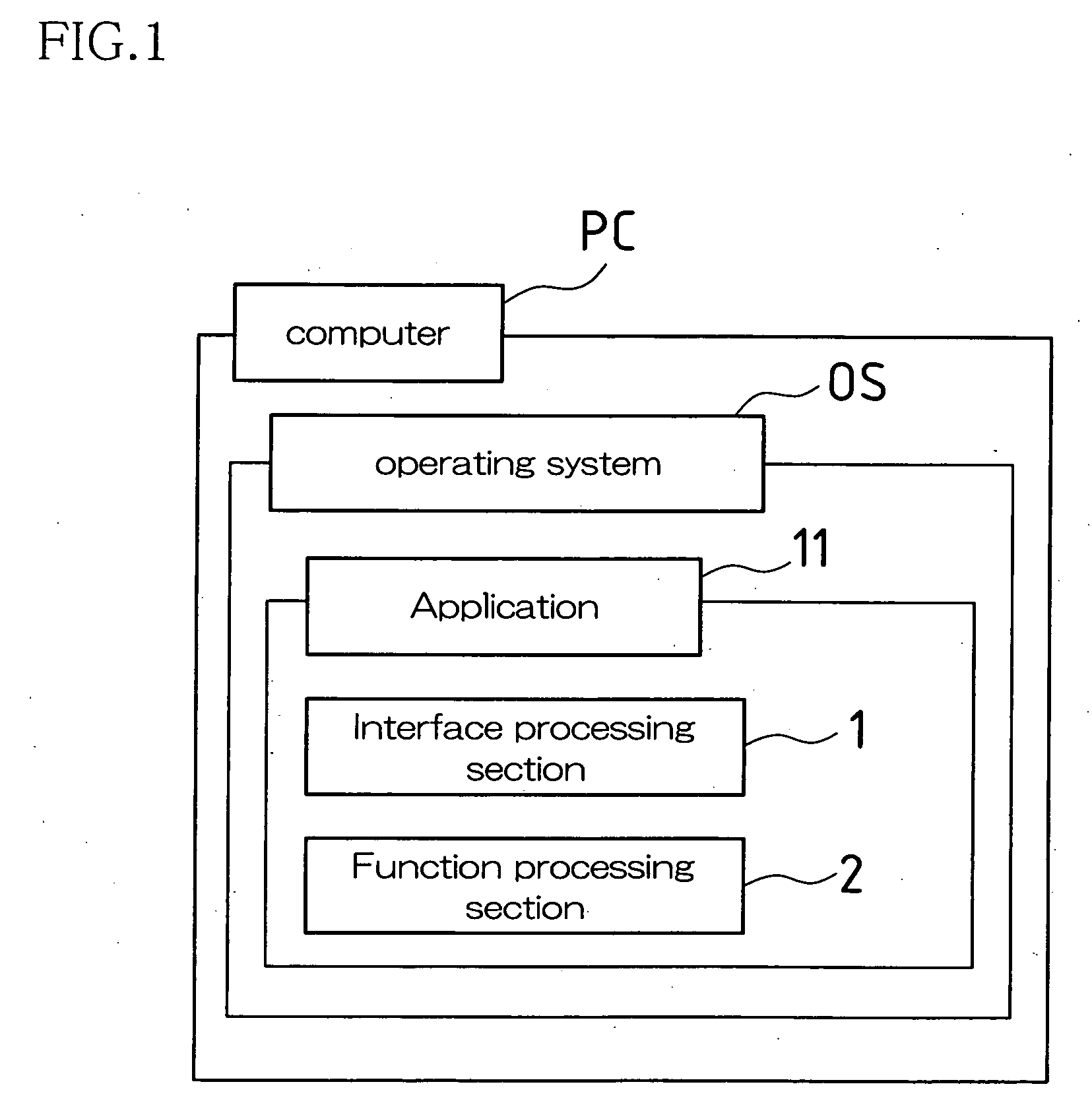
[0049]FIG. 1 is a block diagram illustrating an embodiment of the interface of the present invention. The interface of the present embodiment is constructed by executing application software 11 comprising an interface processing section 1 and a function processing section 2, which implements various functions, based e.g. on an Operating System (hereinafter it is called “OS”) of a Personal Computer (hereinafter it is called “PC”) etc. and operating liquid crystal display units and other display devices, mouse devices and other pointing devices, and printers and other peripheral devices.

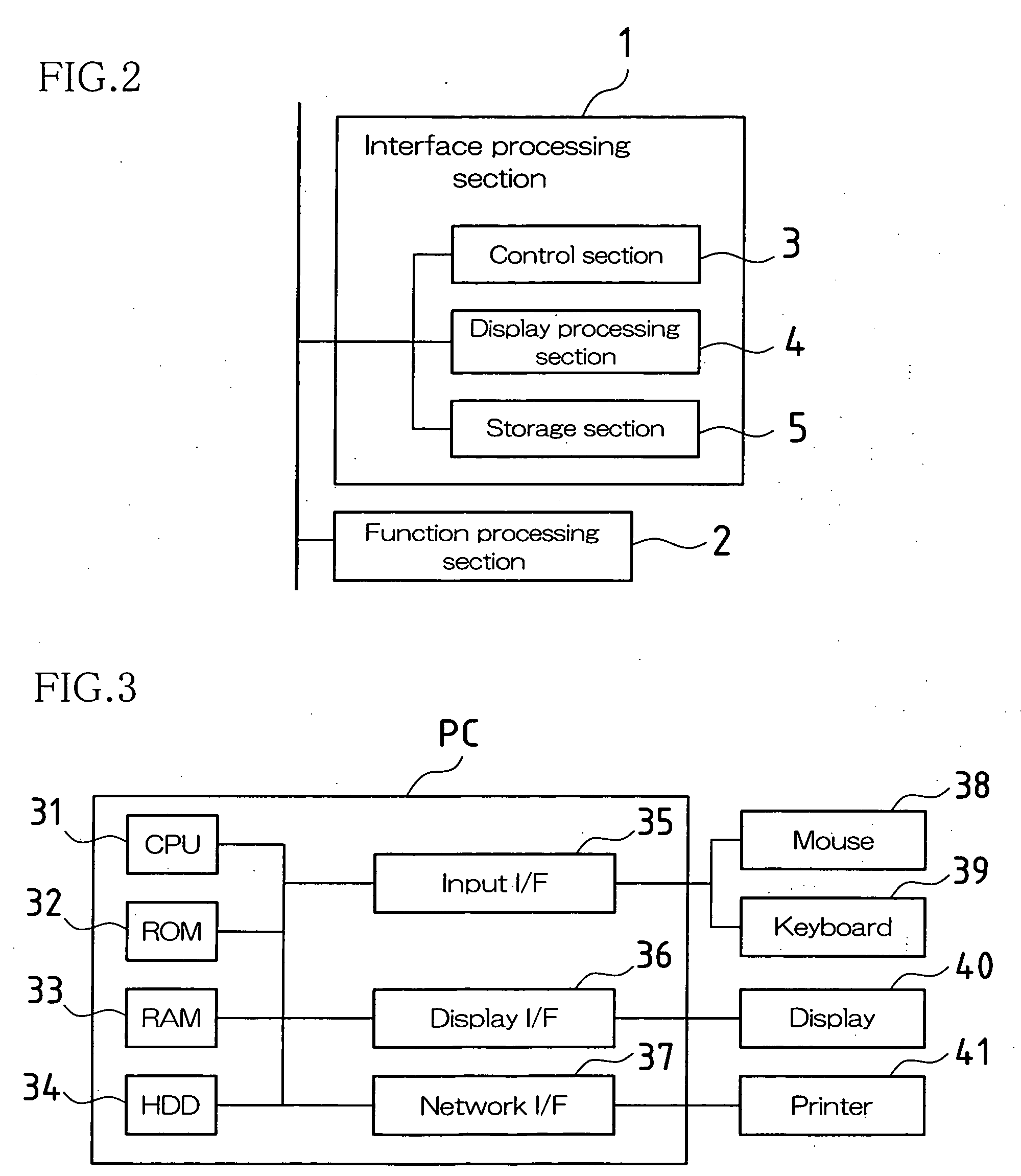
[0050]FIG. 2 is a functional block diagram illustrating the configuration of the application software 11 (application 11 shown in FIG. 2). The interface processing section 1 includes a control section 3, which controls the user interface displayed on the screen of the display devic...


PUM


Abstract

An interface for displaying icons or input control portions corresponding to a plurality of functions on screen and pointing each icon or input control portion on screen selectively includes display control means which, along with repeatedly changing and displaying the icons or the input control portions in succession on screen, designates at least one icon or input control portion among the icons or the input control portions and displays the designated icon(s) or input control portion(s) on a permanent basis.

Description

BACKGROUND OF THE INVENTION [0001] This application claims priority based on Patent Application No. 2005-146926 filed in Japan on May 19, 2005 under Article 119(a) of the U.S. Patent Act. Its entire contents are incorporated herein by reference. [0002] The present invention relates to an interface for selectively pointing a plurality of icons, etc. on screen. [0003] Conventional interfaces of this type include interfaces, in which a plurality of icons are arranged and displayed on the screen of a display device and the functions of application software etc. corresponding to the icons are activated, for instance, by selecting and pointing the desired icons with the help of a pointing device. [0004] Incidentally, in case of a small screen, multiple icons had to be arranged without gaps, which caused icon visibility to deteriorate and made the operation of the icon selection more difficult. [0005] For this reason, for instance, in Japanese Laid-Open Unexamined Patent Application Public...

Claims


Application Information

Patent Timeline
IPC IPC(8): G06F17/00G06F3/048G06F3/0481G06F3/0485
CPCG06F3/0481
Inventor SAWANO, TAKASHI
Owner SHARP KK
Learn More