Device and method of closed-loop level control and for the controlled evacuation of paste masses

a closed-loop level control and mass evacuation technology, applied in the field of vacuum hoppers, can solve the problems of unoptimized degree of mass evacuation, inflow of mass more or less abruptly and uncontrollably, etc., and achieve the effect of better control of the filling level

Active Publication Date: 2007-11-01
ALBERT HANDTMANN MASCHFABRICK
View PDF11 Cites 8 Cited by
  • Summary
  • Abstract
  • Description
  • Claims
  • Application Information

AI Technical Summary

Benefits of technology

[0013] According to the disclosure the valve on the inlet comprises a valve face and a baffle situated opposite, wherein the distance between the face and baffle gives the gap height. Thus, the inlet valve according to the disclosure can be realised in an economical and simple manner.
[0014] According to the disclosure the inlet valve comprises a drive for the baffle for setting the gap height. This drive facilitates an exact setting of the corresponding baffle position or gap height. An embodiment with a fixed baffle and a valve face which is adjustable using a

Problems solved by technology

However, the known techniques exhibit the disadvantage that the inflow of the mass takes place more or less abruptly and uncontrollably.
Also, the d

Method used


Image

  • Device and method of closed-loop level control and for the controlled evacuation of paste masses
  • Device and method of closed-loop level control and for the controlled evacuation of paste masses
  • Device and method of closed-loop level control and for the controlled evacuation of paste masses

Examples


Embodiment Construction

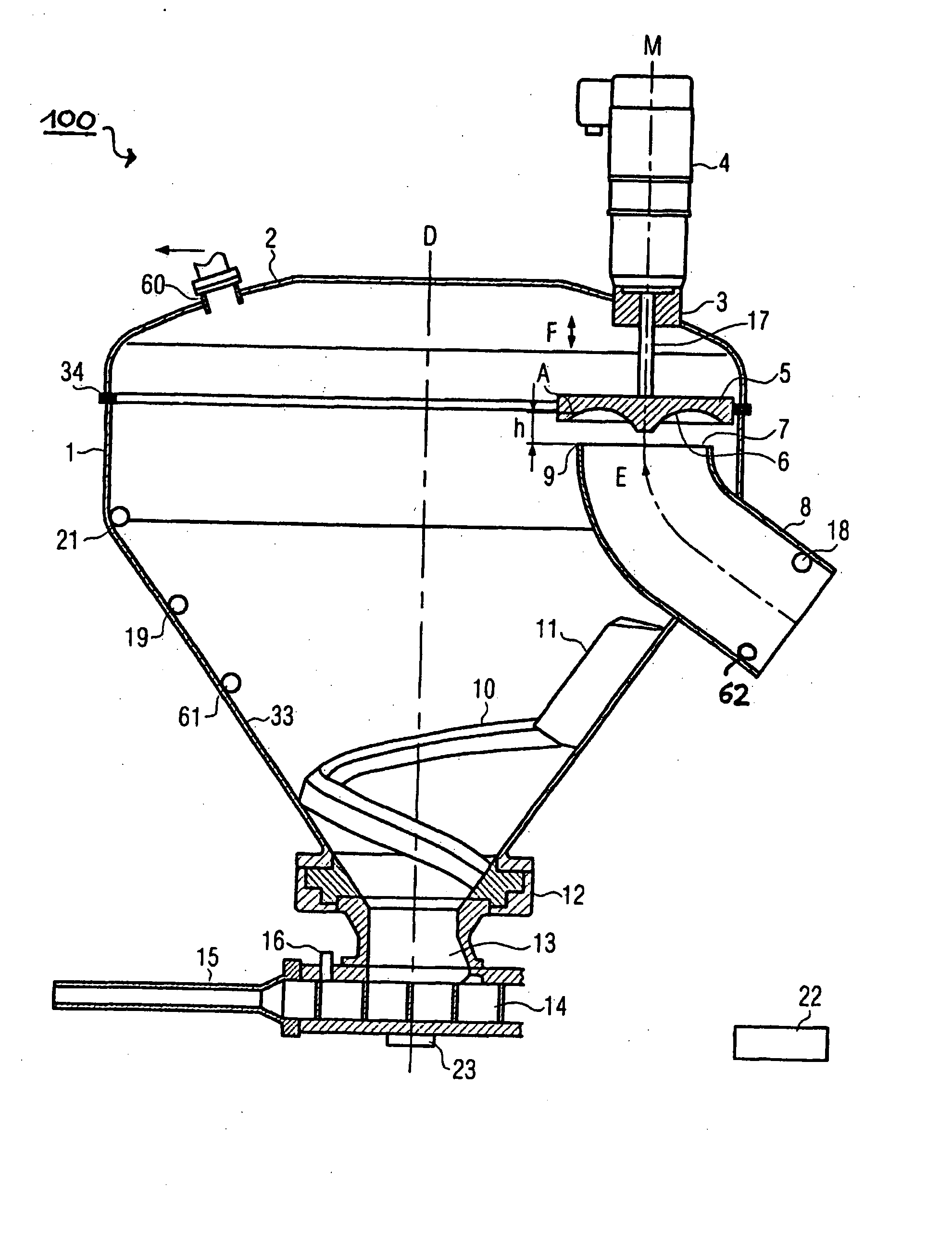
[0036]FIG. 1 shows schematically a vacuum filler 100 according to this disclosure. The vacuum filler 100 comprises a vacuum hopper 1, consisting of a hopper 33 and a lid 2. The hopper 33 and the lid 2 are connected together vacuum-tight via a seal 34, e.g. here a sealing ring. The vacuum hopper 1 comprises an inlet 7 for feeding a paste mass from a reservoir which is not illustrated via the feed tube 8. The hopper 1 also comprises at the lower end, i.e. at the end opposite the lid 2, an outlet 13 for the paste mass. The paste mass situated in the hopper is here conveyed to the center by a circumferential feeder curve 10. The feeder curve 10 here comprises a scraper 11. The feeder curve is in a known manner supported for rotation about the central axis D in the bearing 12 and is rotated in a known manner about the axis D with the aid of a drive which is not illustrated. The scraper 11 here lies adjacent to the interior wall of the hopper 1.

[0037] At the outlet 13 a conveying mechani...


PUM


Abstract

A method and a device for the closed-loop level control and for the controlled evacuation of paste mass, in particular sausage meat, wherein the vacuum hopper comprises an inlet for feeding paste mass, in particular sausage meat, as well as an outlet for ejecting the paste mast an inlet valve, which is arranged at the inlet, wherein a negative pressure can be produced in the vacuum hopper. In order to influence the degree of evacuation in the inflowing mass, the inlet valve comprises in the open state an inlet gap S for the paste mass, the gap height (h) of which can be controlled to influence the degree of evacuation of the paste mass.

Description

CROSS-REFERENCE TO RELATED APPLICATION [0001] The present application claims the benefit of priority of European Patent Application No. 06 044 867.5 filed on Mar. 9, 2006. The entire text of the priority application is incorporated herein by reference in its entirety. FIELD OF THE DISCLOSURE [0002] The disclosure relates to a vacuum hopper for sausage production, a vacuum filler comprising a vacuum hopper of this nature as well as a method for the closed-loop level control and for the controlled evacuation of paste masses. The disclosure also relates to an inlet valve which can be used in the vacuum hopper. BACKGROUND OF THE DISCLOSURE [0003] Normally, during sausage production filling machines are used, the hoppers of which are open at the top. Here, the sausage meat situated in the hopper is transported to the center by a circumferential feeder curve. In the conveying mechanism located at the outlet of the hopper a negative pressure is produced by a vacuum pump in order to extract...

Claims


Application Information

Patent Timeline
IPC IPC(8): A22C11/00A23L13/00
CPCF16K1/36A22C11/02
Inventor MAILE, BERNDSTAUDENRAUSCH, MARTIN
Owner ALBERT HANDTMANN MASCHFABRICK
Why Eureka
Try Eureka