
Tracheostomy tube connector key system

a tracheostomy tube and key system technology, applied in the field of medical devices, can solve the problems of patient improper fitting of tracheostomy tubes, confusion as to the proper size of inner cannulas, etc., and achieve the effect of improving the reliability of attachment and maintaining attachment retention

Inactive Publication Date: 2007-11-01
TYCO HEALTHCARE GRP LP
View PDF15 Cites 31 Cited by
  • Summary
  • Abstract
  • Description
  • Claims
  • Application Information

AI Technical Summary

Benefits of technology

[0009] Improving the reliability of attachment and continued attachment retention of the inner cannula to the outer cannula may be desired. Also, an added benefit would be to do so without having to change existing designs for the inner cannula and connector.
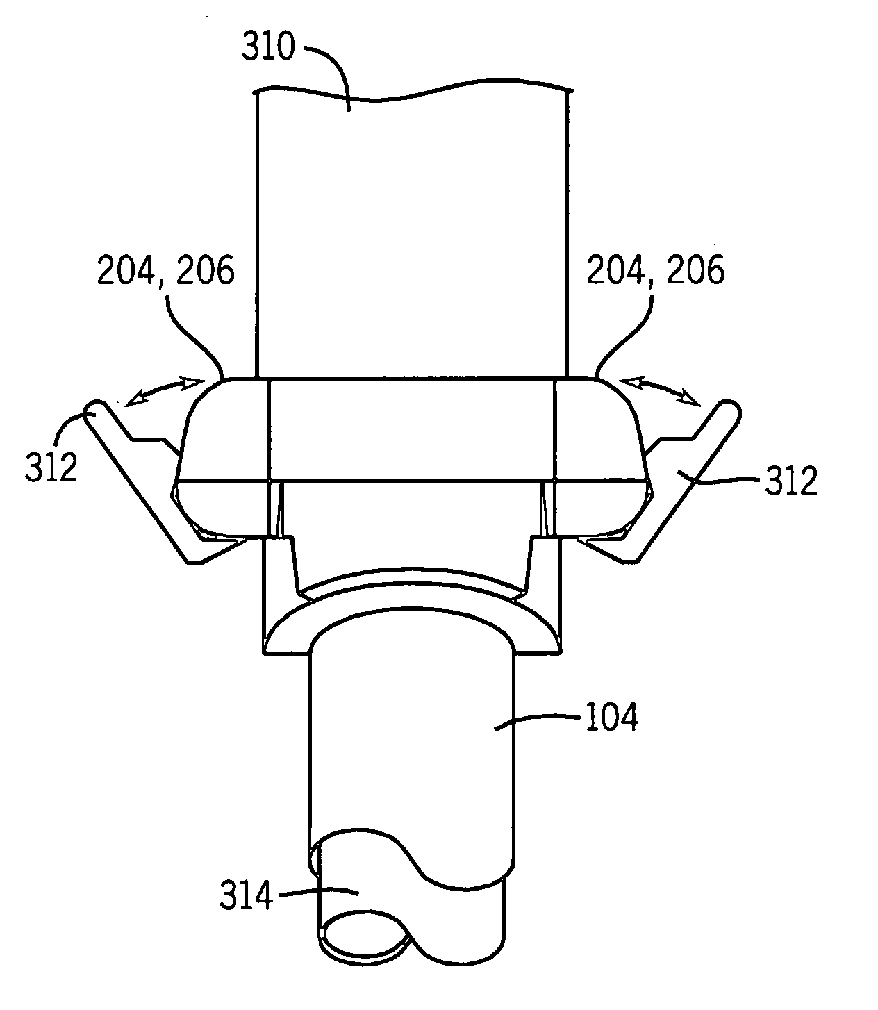
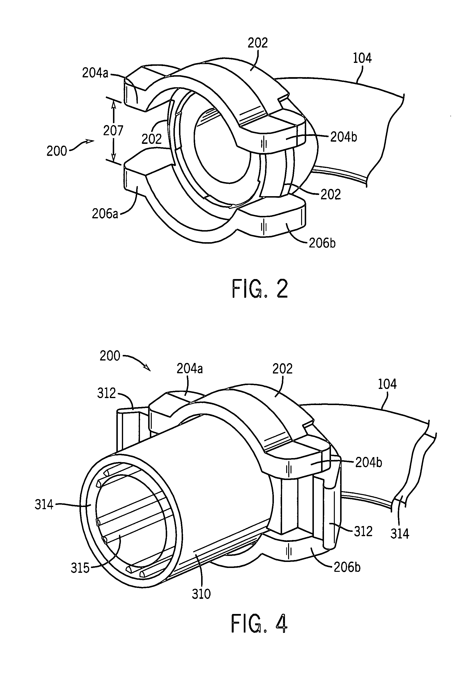
[0012] In accordance with embodiments of the present technique, an outer cannula assembly is provided. The outer cannula assembly comprises an outer cannula, and an outer cannula connector comprising two or more support ears. Further, the two or more support ears are configured to substantially prevent rotation of an inner cannula connector when the inner cannula connector is engaged with the outer cannula connector.
[0013] In accordance with embodiments of the present technique, a medical device tube is provided. The medical device tube comprises an outer cannula comprising an outer cannula connector. Further, the outer cannula connector comprises two or more support ears; and an inner cannula comprising an inner cannula connector comprising one or more locking ears. Accordingly, the one or more locking ears engage the two or more support ears to substantially prevent rotation of the inner cannula connector relative to the outer cannula connector when the inner cannula connector is engaged with the outer cannula connector.

Problems solved by technology

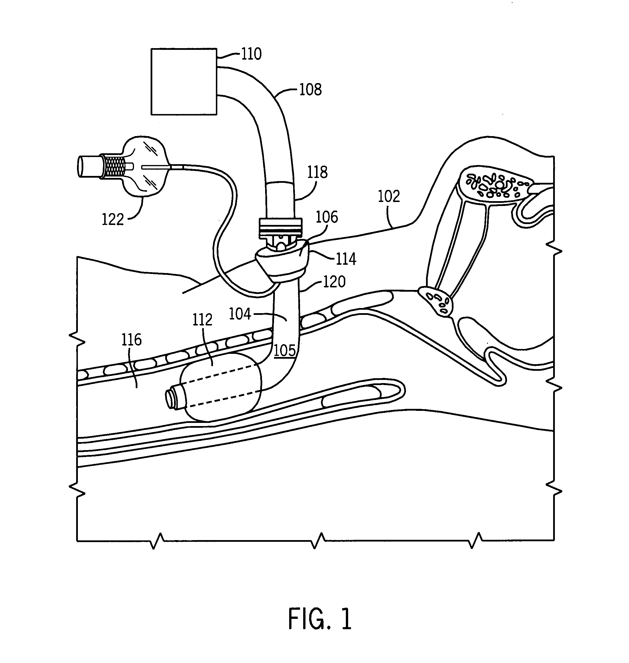
Thus, a clinician may be provided with a variety of sizes of inner and / or outer cannulas that may lead to confusion as to the proper size of inner cannula to insert in an outer cannula.
However, the apparent fitting of the outer and inner cannulas may conceal their mismatch, such that the patient may be improperly fitted with the tracheostomy tube.

Method used


Image

  • Tracheostomy tube connector key system
  • Tracheostomy tube connector key system
  • Tracheostomy tube connector key system

Examples


Embodiment Construction

[0034] One or more specific embodiments of the present invention will be described below. In an effort to provide a concise description of these embodiments, not all features of an actual implementation are described in the specification. It should be appreciated that in the development of any such actual implementation, as in any engineering or design project, numerous implementation-specific decisions must be made to achieve the developers' specific goals, such as compliance with system-related and business-related constraints, which may vary from one implementation to another. Moreover, it should be appreciated that such a development effort might be complex and time consuming, but would nevertheless be a routine undertaking of design, fabrication, and manufacture for those of ordinary skill having the benefit of this disclosure.

[0035] Referring now to the drawings, the details of specific example embodiments are schematically illustrated. Like elements in the drawings will be r...


PUM


Abstract

A tracheostomy tube is proved. The tracheostomy tube includes an outer cannula that comprises an outer cannula connector comprising a first keying feature. The tracheostomy tube further comprises an inner cannula comprising an inner cannula connector including a second keying feature configured to complement the first keying feature when the inner cannula is inserted into the outer cannula. Further, a method is provided, whereby the method comprises inserting an outer cannula into a patient's trachea, and inserting an inner cannula into the outer cannula such that a keying feature on an inner cannula connector of the inner cannula engages a complementary keying feature on an outer cannula connector of the outer cannula.

Description

CROSS REFERENCE TO RELATED APPLICATIONS [0001] This application is a Continuation-in-Part of U.S. patent application Ser. No. 11 / 237,168, titled “Medical Device Tube Having a Flange With Opposing Support Ears for Improved Alignment and Retention of an Inner Cannula in an Outer Cannula,” filed Sep. 28, 2005, herein incorporated by reference in its entirety.BACKGROUND OF THE INVENTION [0002] 1. Field of the Invention [0003] The present disclosure, according to one embodiment, relates to medical device tubes, e.g., tracheostomy tubes, used in medical applications, and more particularly, to more securely attaching an inner cannula to an outer cannula of a trachostomy tube. [0004] 2. Description of the Related Art [0005] This section is intended to introduce the reader to various aspects of art that may be related to various aspects of the present invention, which are described and / or claimed below. This discussion is believed to be helpful in providing the reader with background informa...

Claims


Application Information

Patent Timeline
Patent Type & Authority Applications(United States)
IPC IPC(8): A61M39/10
CPCA61M16/0434A61M16/0465A61M16/0488A61M16/0427A61M16/0816A61M2205/6045A61M16/08
Inventor MATLOCK, GEORGE L.BRACKNEY, STEVEN M.IGNACIO, AVILA
Owner TYCO HEALTHCARE GRP LP
Learn More