Lane departure prevention apparatus and method

a technology control apparatus, which is applied in the direction of anti-collision systems, non-deflectable wheel steering, underwater vessels, etc., can solve the problems of control short time period of lane departure prevention control, and bringing an uncomfortable feeling to the passenger

Inactive Publication Date: 2007-11-01
NISSAN MOTOR CO LTD
View PDF10 Cites 70 Cited by
  • Summary
  • Abstract
  • Description
  • Claims
  • Application Information

AI Technical Summary

Benefits of technology

[0003]However, there is a possibility that a driver perceives a time period of lane departure prevention control to be short as compared with a magnitude of yaw angle, in the case where the lane departure prevention control is carried out under the situation where the yaw angle of vehicle relative to the traveling lane becomes large, for example, when the vehicle is running at an entrance (beginning) of a curve. Namely, a time period during which the passenger is receiving a control feeling of lane departure prevention control becomes short, and thereby the lane departure prevention control brings an uncomfortable feeling to the passenger. Accordingly, it is conceivable that the time period during which the passenger is receiving the control feeling of lane departure prevention control is elongated by making a start timing of lane departure prevention control earlier than its normal timing. However, in this case; an execution frequency of lane departure prevention control is made high on a normal traveling road (e.g., straight pathway), and thereby the lane departure prevention control brings an uncomfortable feeling to the passenger.

Problems solved by technology

However, there is a possibility that a driver perceives a time period of lane departure prevention control to be short as compared with a magnitude of yaw angle, in the case where the lane departure prevention control is carried out under the situation where the yaw angle of vehicle relative to the traveling lane becomes large, for example, when the vehicle is running at an entrance (beginning) of a curve.
Namely, a time period during which the passenger is receiving a control feeling of lane departure prevention control becomes short, and thereby the lane departure prevention control brings an uncomfortable feeling to the passenger.
However, in this case; an execution frequency of lane departure prevention control is made high on a normal traveling road (e.g., straight pathway), and thereby the lane departure prevention control brings an uncomfortable feeling to the passenger.

Method used


Image

  • Lane departure prevention apparatus and method
  • Lane departure prevention apparatus and method
  • Lane departure prevention apparatus and method

Examples


first embodiment

[0039](Structures)

[0040]In a first embodiment of the present invention, a rear-wheel drive vehicle equipped with the lane departure (deviation) prevention apparatus according to the present invention is exemplified. The rear-wheel drive vehicle is equipped with an automatic transmission, a conventional differential gear, and a braking system capable of independently controlling braking forces of left and right wheels of the front end and also capable of independently controlling braking forces of left and right wheels of the rear end.

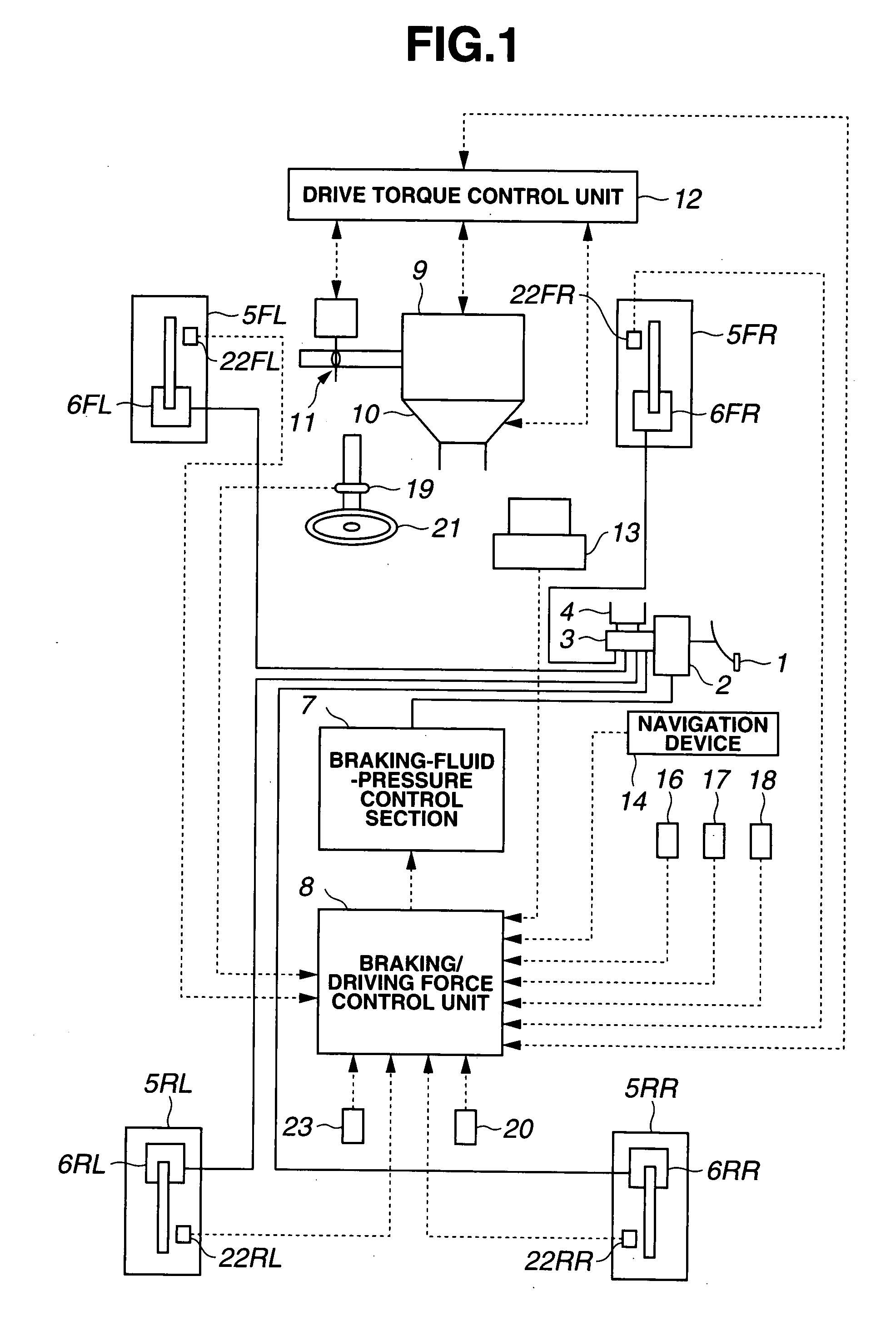
[0041]FIG. 1 is a schematic structural diagram showing the first embodiment. As shown in FIG. 1, the braking system includes a brake pedal 1, a booster 2, a master cylinder(s) 3, and a reservoir 4. Generally, braking fluid pressure boosted by master cylinder 3 is supplied to wheel cylinders 6FL to 6RR of respective wheels 5FL to 5RR in accordance with the degree of depression of brake pedal 1 by a driver. A braking-fluid-pressure control section 7 is pr...

second embodiment

[0118]Next, a second embodiment according to the present invention will be explained below.

[0119](Structures)

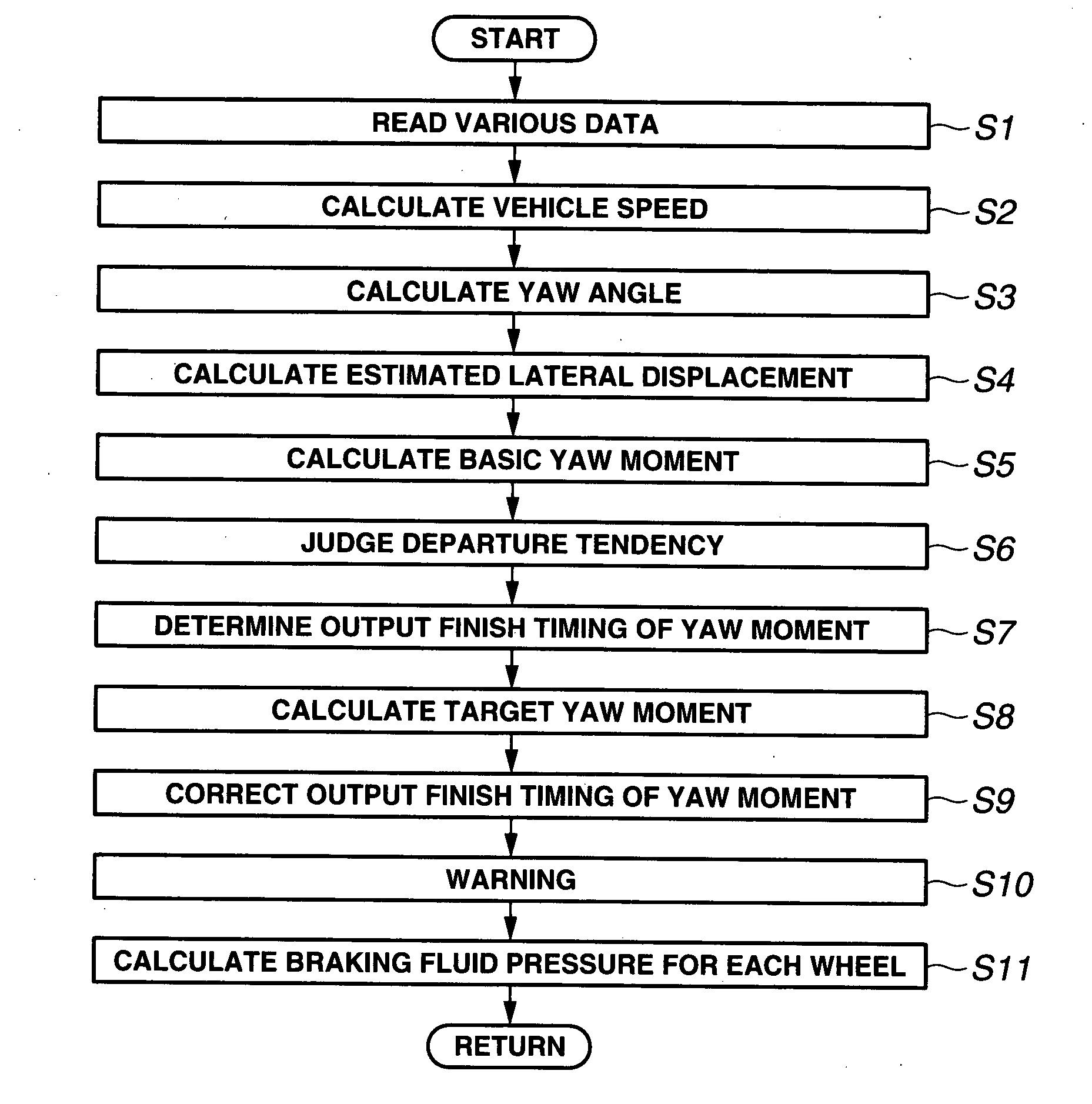
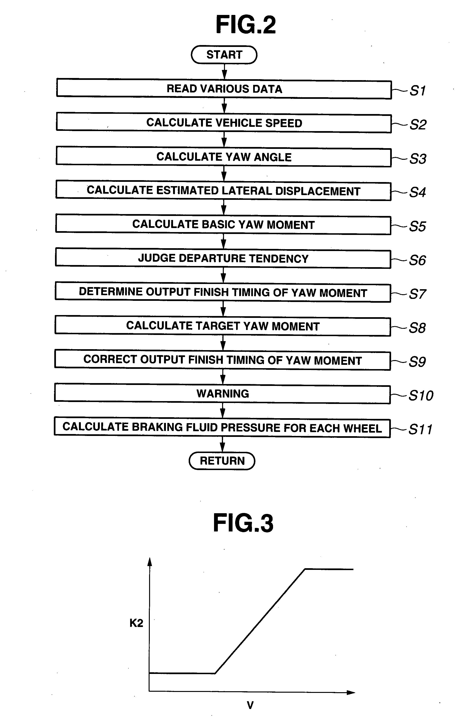
[0120]In the second embodiment, a rear-wheel drive vehicle equipped with the lane departure prevention apparatus according to the present invention is exemplified in the similar manner as the first embodiment. In the second embodiment, a procedure of computing process that is executed in braking / driving force control unit 8 is same as the procedure shown in FIG. 2, namely similar as the procedure in the first embodiment. However, the correction of output finish timing for yaw moment at step S9 is different from that of the first embodiment. Namely, at step S9 in the second embodiment, the output finish timing for yaw moment is corrected by correcting decrease-side variation limiter Ldown set at step S8.

[0121]FIG. 15 shows a procedure for correcting the output finish timing of yaw moment in the second embodiment. As shown in FIG. 15, the controller judges whether or not the ve...

third embodiment

[0130]Next, a third embodiment according to the present invention will be explained below.

[0131](Structures)

[0132]In the third embodiment, a rear-wheel drive vehicle equipped with the lane departure prevention apparatus according to the present invention is exemplified in the similar manner as the first embodiment. In the third embodiment, a procedure of computing process that is executed in braking / driving force control unit 8 is same as the procedure shown in FIG. 2, namely similar as the procedure in the first embodiment. However, the correction of output finish timing for yaw moment at step S9 is different from that of the first embodiment. Namely, at step S9 in the third embodiment, the output finish timing for yaw moment is corrected by maintaining or holding basic yaw moment MS 0 obtained at the time of finish of lane departure prevention control, for a predetermined time period.

[0133]FIG. 18 shows a procedure for correcting the output finish timing of yaw moment in the third...


PUM


Abstract

A lane departure prevention apparatus includes a control section configured to carry out a lane departure prevention control to prevent a vehicle from departing from a lane, and to finish the lane departure prevention control by using a predetermined finish parameter; a vehicle-state detecting section configured to detect a state of vehicle at least when or after the lane departure prevention control is started; and a control finish-parameter correcting section configured to correct the predetermined finish parameter on the basis of the vehicle state detected by the vehicle-state detecting section.

Description

BACKGROUND OF THE INVENTION[0001]The present invention relates to apparatus and / or method for preventing a vehicle from departing from a lane when the vehicle comes close to departing.[0002]Japanese Patent Published Application No. 2003-154910 discloses a previously-proposed lane departure prevention apparatus which is adapted to prevent a vehicle from departing from a traveling lane by applying a yaw moment to the vehicle in the case where it is determined that the vehicle has a tendency to depart from the lane. Moreover, Japanese Patent Published Application No. 2003-112540 discloses another previously-proposed lane departure prevention apparatus.SUMMARY OF THE INVENTION[0003]However, there is a possibility that a driver perceives a time period of lane departure prevention control to be short as compared with a magnitude of yaw angle, in the case where the lane departure prevention control is carried out under the situation where the yaw angle of vehicle relative to the traveling ...

Claims


Application Information

Patent Timeline
Patent Type & Authority Applications(United States)
IPC IPC(8): G06G7/76G06F19/00
CPCB60T8/17551B60T8/17557B60W30/12B60T2201/086B60T2201/08
Inventor HAYAKAWA, YASUHISAIWASAKA, TAKESHI
Owner NISSAN MOTOR CO LTD
Why Eureka
Try Eureka