Combined variable compression ratio and passive ignition system

a variable compression ratio and ignition system technology, applied in the direction of combustion engines, machines/engines, cylinders, etc., can solve the problems of unreliable control of the necessary oil flow, create some turbulence, etc., and achieve the effect of rapid increase in compression pressure, more positive ignition, and quick respons

Inactive Publication Date: 2007-11-08
ANDERSSON PER GOSTA EDVIN +1
View PDF18 Cites 8 Cited by
  • Summary
  • Abstract
  • Description
  • Claims
  • Application Information

AI Technical Summary

Benefits of technology

[0012] The present invention provides the very precise feedback and quick response times absent from the prior art. T

Problems solved by technology

In diesel systems, the fuel injection nozzle creates some turbulence as the fuel is injected into the combustion space.
One method is to use hydraulics supplie

Method used


Image

  • Combined variable compression ratio and passive ignition system
  • Combined variable compression ratio and passive ignition system
  • Combined variable compression ratio and passive ignition system

Examples


Embodiment Construction

[0018] In the following figures, the same reference numerals will be used to refer to the same components. In the following description, various operating parameters and components are described for plural constructed embodiments. These specific parameters and components are included as examples and are not meant to be limiting.

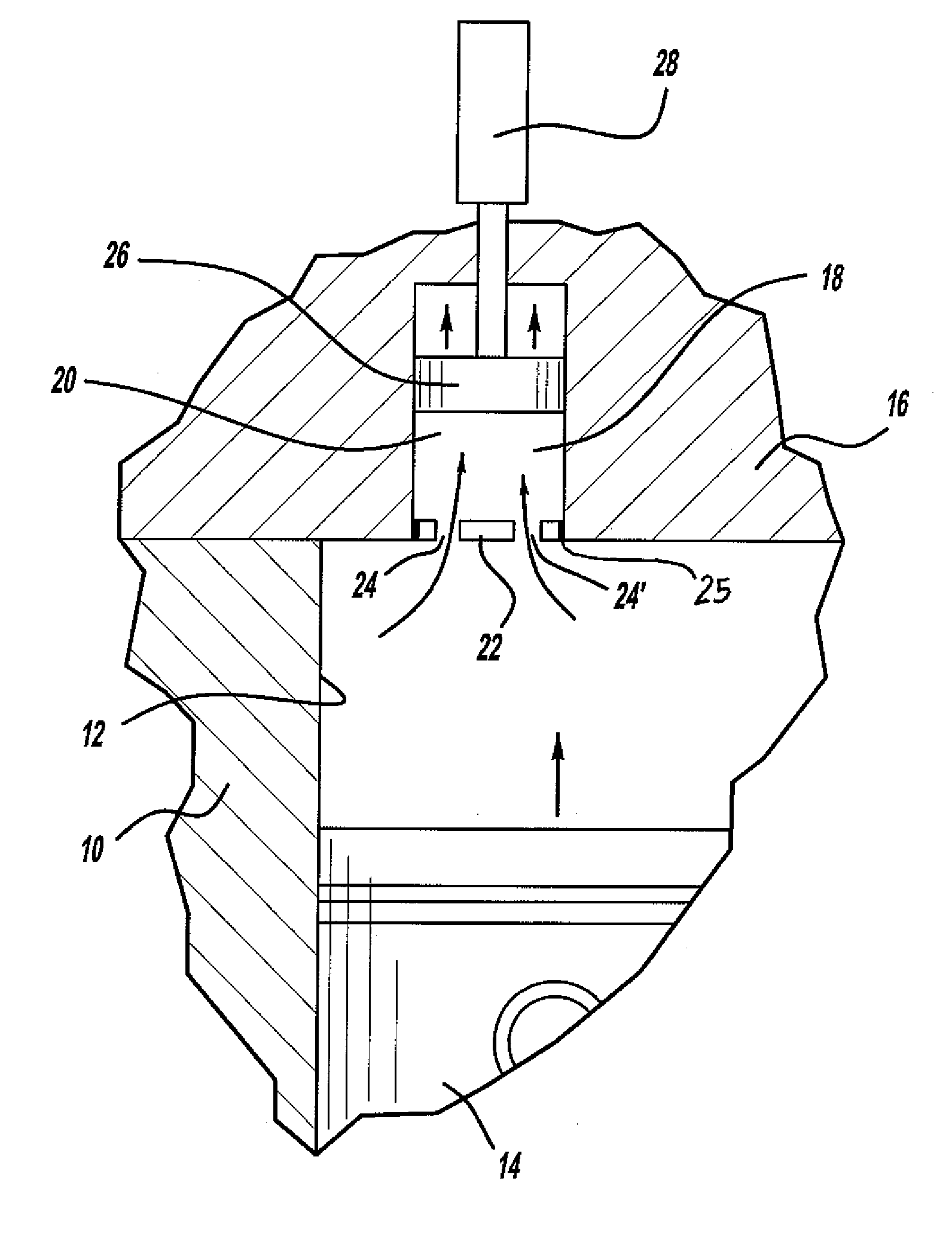
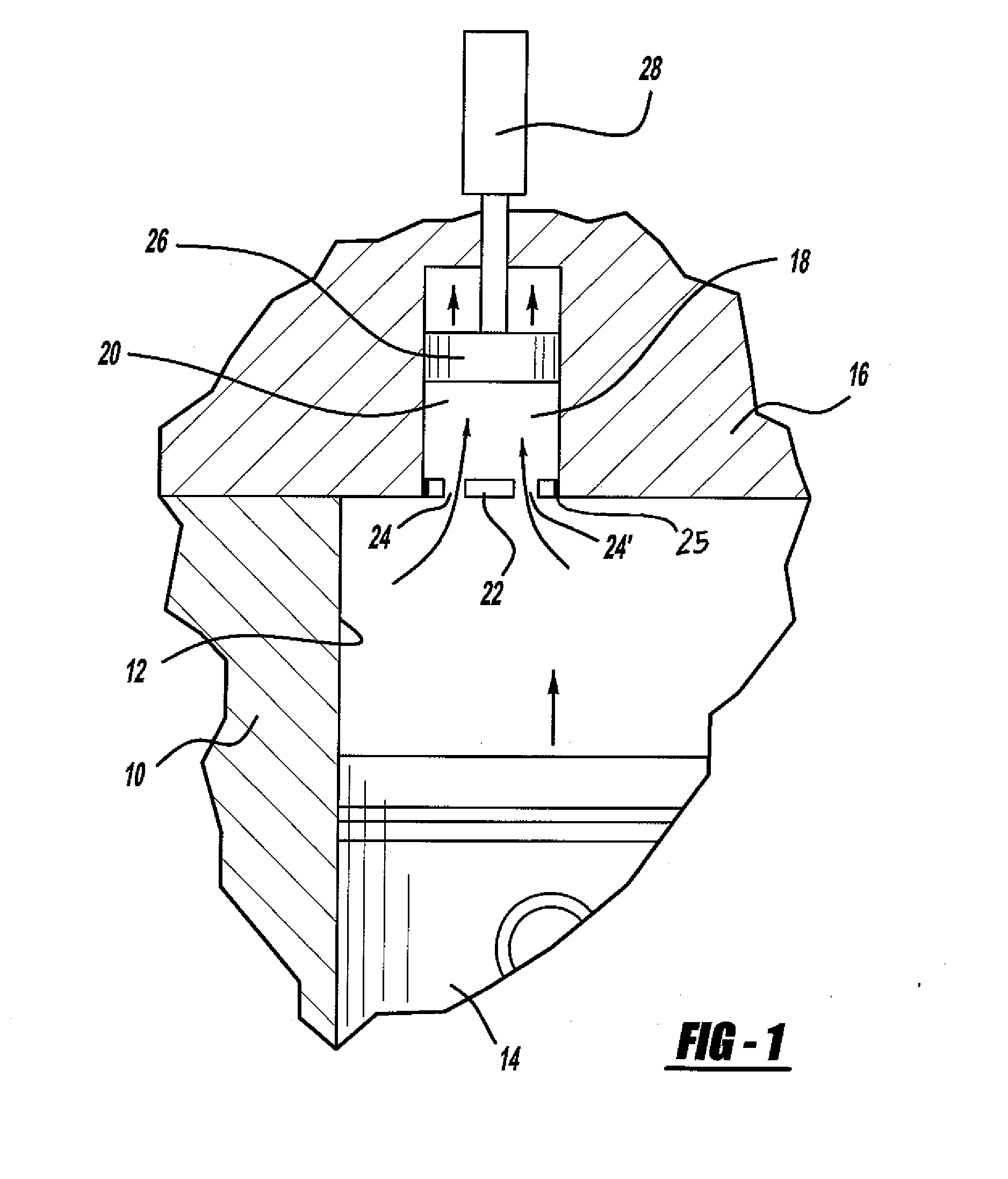
[0019] With reference to FIG. 1, an engine block 10 is illustrated. The configuration of the engine block 10 is shown only for illustrative purposes and is not intended as being limiting. The engine block 10 may find utility in any one of a variety of applications, including automotive vehicles and trucks.

[0020] The engine block 10 has a main cylinder 12 formed therein. A main piston 14 is reciprocatingly provided in the main cylinder 12 in a known manner. The open upper end of the main cylinder 12 is closed by a cylinder head 16. Conventional engine elements such as intake valves, exhaust valves, a connecting rod and a crankshaft are not illustrated as the...


PUM


Abstract

An arrangement for a reciprocating internal combustion engines is provide that includes a reciprocating main piston and a smaller cell piston which works in cooperation with the main piston to vary the compression ratio of and igniting a fuel-air mixture in a homogenous compression ignition engine. An actuator controls movement of the smaller cell piston relative to movement of the main piston.

Description

TECHNICAL FIELD [0001] The embodiment of the disclosed invention relates generally to reciprocating internal combustion engines. More particularly the present invention relates to an engine having a reciprocating main piston and a smaller cell piston which works in cooperation with the main piston to vary the compression ratio of and igniting a fuel-air mixture in a homogenous compression ignition engine. BACKGROUND OF THE INVENTION [0002] Many forms of non-spark ignition systems are know for use in internal combustion engines. One of the oldest arrangements is the hot bulb ignition typically used with fuels such as crude oil, vegetable oil, and diesel fuel. An external heat source such as a flame is used to heat a protrusion on the engine head known as a bulb. Once the bulb is hot enough, the engine can be started by turning the flywheel. The compression of the air-fuel mixture and the heat in the bulb caused the fuel to ignite and, once working, the bulb would stay hot enough to k...

Claims


Application Information

Patent Timeline
IPC IPC(8): F02F1/24
CPCF01B31/14F02D15/04F02B75/042F02B1/12
Inventor ANDERSSON, PER GOSTA EDVINBROGDON, JAMES WILLIAM
Owner ANDERSSON PER GOSTA EDVIN
Why Eureka
Try Eureka