Humidity control algorithm

Inactive Publication Date: 2007-11-08
ROBERTSHAW CONTROLS CO
View PDF8 Cites 40 Cited by
  • Summary
  • Abstract
  • Description
  • Claims
  • Application Information

AI Technical Summary

Benefits of technology

[0012]Alternatively, the method could be further enhanced by providing a temperature probe at an outlet vent for the HVAC system. By observing the temperature at the outlet vent, rather than at the thermostat or control itself, the thermostat cou

Problems solved by technology

However, currently available thermostats and HVAC controllers are not capable of operating the HVAC system as a dehumidifier independently when the temperature within the building is below the cooling temperature set point such that a demand for cooling is not indicated.
In these situations, the therm

Method used


Image

  • Humidity control algorithm
  • Humidity control algorithm
  • Humidity control algorithm

Examples


Embodiment Construction

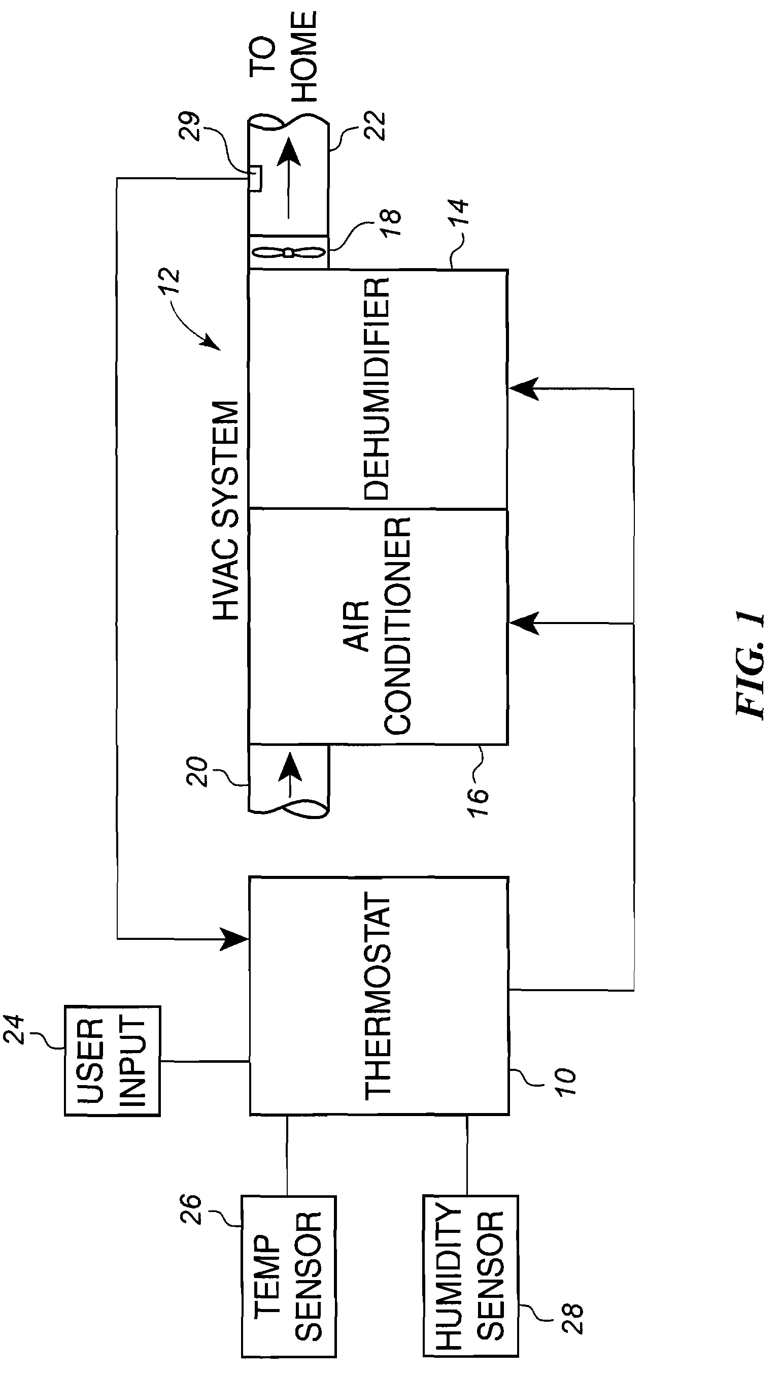
[0018]Referring now to FIG. 1, thereshown is a thermostat 10 connected to an HVAC system 12 that includes both a dehumidifier 14 and an air conditioner 16. The HVAC system includes a blower 18 that draws a supply of air through an inlet duct 20 from the indoor air environment being conditioned through the HVAC system 12 and out of an outlet duct 22 for return to the home.

[0019]The thermostat 10 includes a user input 24 that allows the home occupant to enter the desired set point temperature for heating and cooling. Further, the user input 24 allows the home occupant to enter a desired set point for the relative humidity within the home. The thermostat 10 receives a temperature signal from the temperature sensor 26 and a humidity signal from the humidity sensor 28. Typically, the temperature sensor 26 and humidity sensor 28 are incorporated directly into the thermostat 10. However, the temperature sensor 26 and humidity sensor 28 can be located remotely from the thermostat and commun...


PUM


Abstract

A system and method is provided to control the operation of an HVAC system to remove humidity from an indoor air environment without cooling the indoor air environment. The system includes a thermostat that operates the HVAC system to remove humidity when the sensed humidity falls below a humidity set point. After operation of the HVAC system, the thermostat monitors whether the temperature within the indoor air environment falls due to the operation of the HVAC system. If the temperature within the indoor air environment falls consistently, the humidity control algorithm determines that the HVAC system cannot operate without cooling and prevents future operation of the HVAC system to provide only dehumidification. If, however, the humidity control algorithm determines that the HVAC system can operate to dehumidify without cooling, the humidity control algorithm operates the HVAC system accordingly.

Description

CROSS REFERENCE TO RELATED APPLICATION[0001]The present application is based on and claims priority from U.S. Provisional Patent Application Ser. No. 60 / 797,633 filed on May 4, 2006.BACKGROUND OF THE INVENTION[0002]Recently, there have been many advancements in the operation of HVAC systems regarding humidity control. In particular, there currently exist HVAC systems that are capable of removing humidity from the air without cooling the air. In many of these systems, humidity is removed from the air and, once the humidity has been removed, the dehumidified air is heated enough such that the air returned to the enclosed environment has not been cooled.[0003]As with many technological advances, the controls and control algorithms for HVAC systems have lagged the advances in the physical equipment. Presently, thermostats or HVAC controls only call for dehumidification when there is also a call for cooling or when the current temperature of the indoor air environment is close to the coo...

Claims


Application Information

Patent Timeline
IPC IPC(8): F24F3/14
CPCF24F3/14F24F11/0015F24F11/0012F24F11/0008F24F11/30F24F2110/10F24F2110/20F24F11/76F24F11/56F24F11/65
Inventor CHAPMAN, JOHN G.CATLIN, GEORGE N.
Owner ROBERTSHAW CONTROLS CO
Why Eureka
Try Eureka