Water jacket spacer

A water jacket and bushing technology, applied in liquid cooling, engine components, cylinders, etc., can solve the problem of excessive cooling water capacity of the water jacket, and achieve the effects of simple cooling, simple homogenization, and easy manufacturing.

A water jacket and bushing technology, applied in liquid cooling, engine components, cylinders, etc., can solve the problem of excessive cooling water capacity of the water jacket, and achieve the effects of simple cooling, simple homogenization, and easy manufacturing.

CN102606334AInactive Publication Date: 2012-07-25UCHIYAMA MFG

Image

  • Water jacket spacer
  • Water jacket spacer
  • Water jacket spacer

Examples


Embodiment Construction

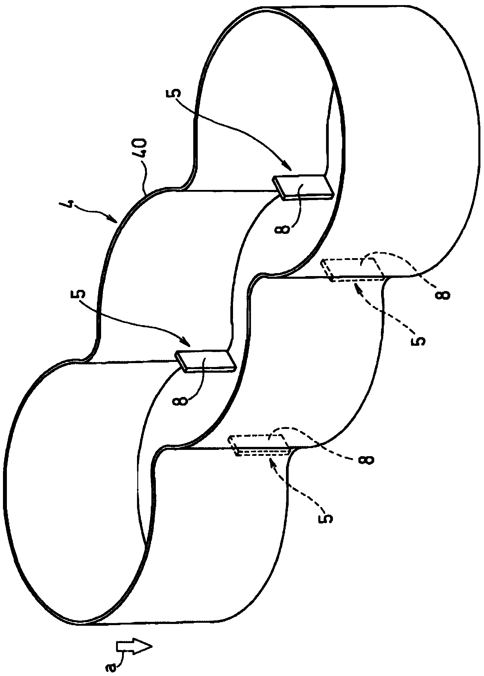
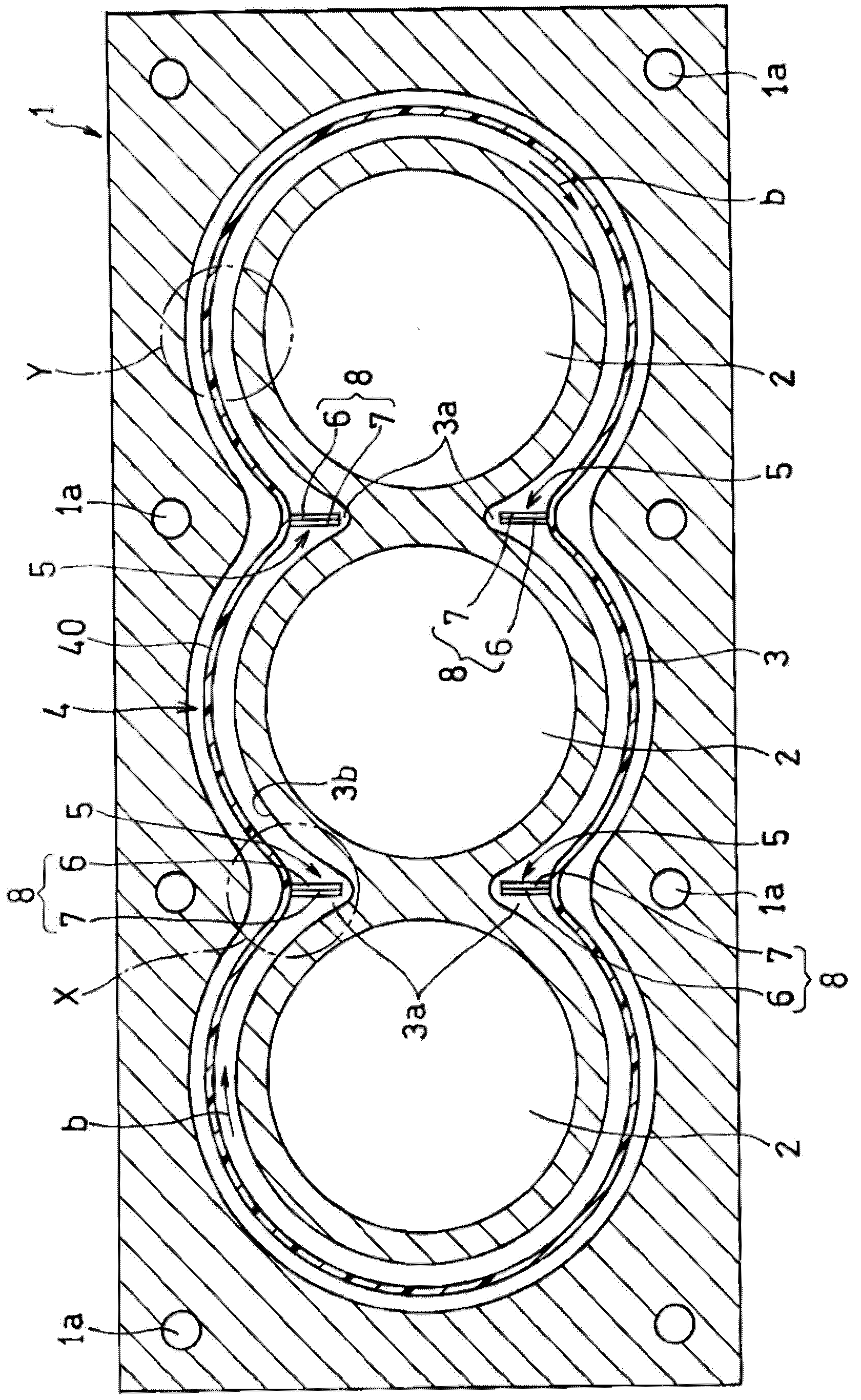
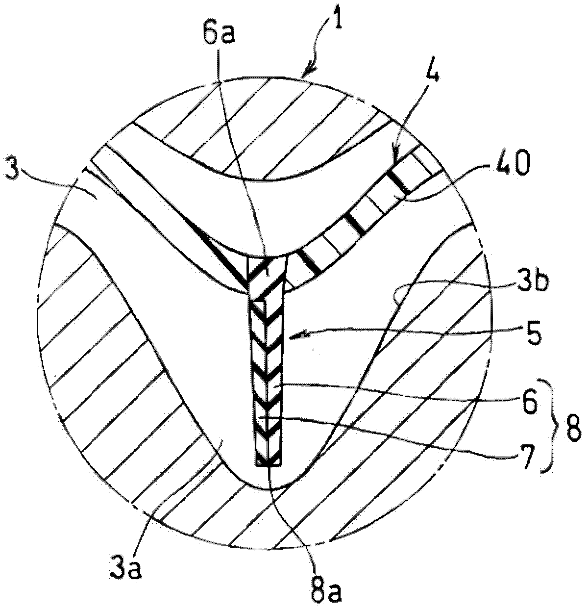
[0051] Embodiments of the present invention will be described below based on the drawings. figure 1 It is a schematic overall perspective view of one embodiment of the water jacket bushing of the present invention, figure 2 It is a schematic cross-sectional plan view of a cylinder block of a water-cooled engine provided with a water jacket fitted with the water jacket liner. figure 2 The cylinder block 1 shown is a cylinder block of a three-cylinder engine, and has three cylinder bores 2 arranged in series. The surface on one side) is excavated and is formed with the water jacket 3 of open channel type with bottom. Actually, the cylinder block 1 is made of a cast product such as aluminum alloy, so the water jacket 3 is formed of a male mold of a casting mold. In addition, in the cylinder block 1, a plurality of female screw holes 1a for integrally fastening a cylinder head (not shown) together with bolts are formed on the upper surface. In the portion between the adjacent...


PUM


Abstract

A water jacket spacer has a spacer body molded in conformity to the shape of the water jacket and a regulating member whose one side is fixed to the spacer body. The regulating member is composed of a first member which is not water-swellable and is elastically deformable and a second member made of water-swellable elastomer which is integrally fixed to the first member. The regulating member lies in a state not-contacting an opposed wall of the water jacket when inserted into the water jacket together with the spacer body, whereas it blocks a part of cooling water flowing through the water jacket by deforming such that a side of the regulating member not fixed to the spacer body faces toward the opposed wall of the water jacket when the second member swells by absorbing cooling water flown into the water jacket and thereby the first member is elastically deformed.

Description

technical field [0001] The present invention relates to a water jacket liner embedded in a water jacket of a cylinder block for adjusting the flow capacity of cooling water in the water jacket. Background technique [0002] There are open channel type and closed channel type in the cooling structure of the cylinder block in the internal combustion engine, especially the water-cooled engine, through the water jacket. The cooling structure of the open channel type is formed by forming an annular water jacket with an open upper end such as an oblong shape in plan view or a substantially oblong shape with a constricted neck around the cylinder bore of the cylinder block, so that the cooling water flows and circulates to the coupling. The cylinder head and the upper end are enclosed in a water jacket to cool the engine block. [0003] Generally, the cylinder block is manufactured by casting aluminum alloy or the like. Casting is carried out by filling casting material into a mo...

Claims


Application Information

Patent Timeline
25 Jul 2012
Publication
CN102606334A
IPC
F02F1/16; F02F1/10
CPC
F02F1/10; F02F1/14; F02F1/16; F01P3/02
Inventors
松木克则; 长门贵之