Refrigerator
A technology of refrigerators and cooling fans, applied in the field of refrigerators, which can solve problems such as low temperature, overcooling of stored objects, and inability to cool stored objects, and achieve the effect of improving antibacterial properties and freshness preservation
- Summary
- Abstract
- Description
- Claims
- Application Information
AI Technical Summary
Problems solved by technology
Method used
Image
Examples
no. 1 approach
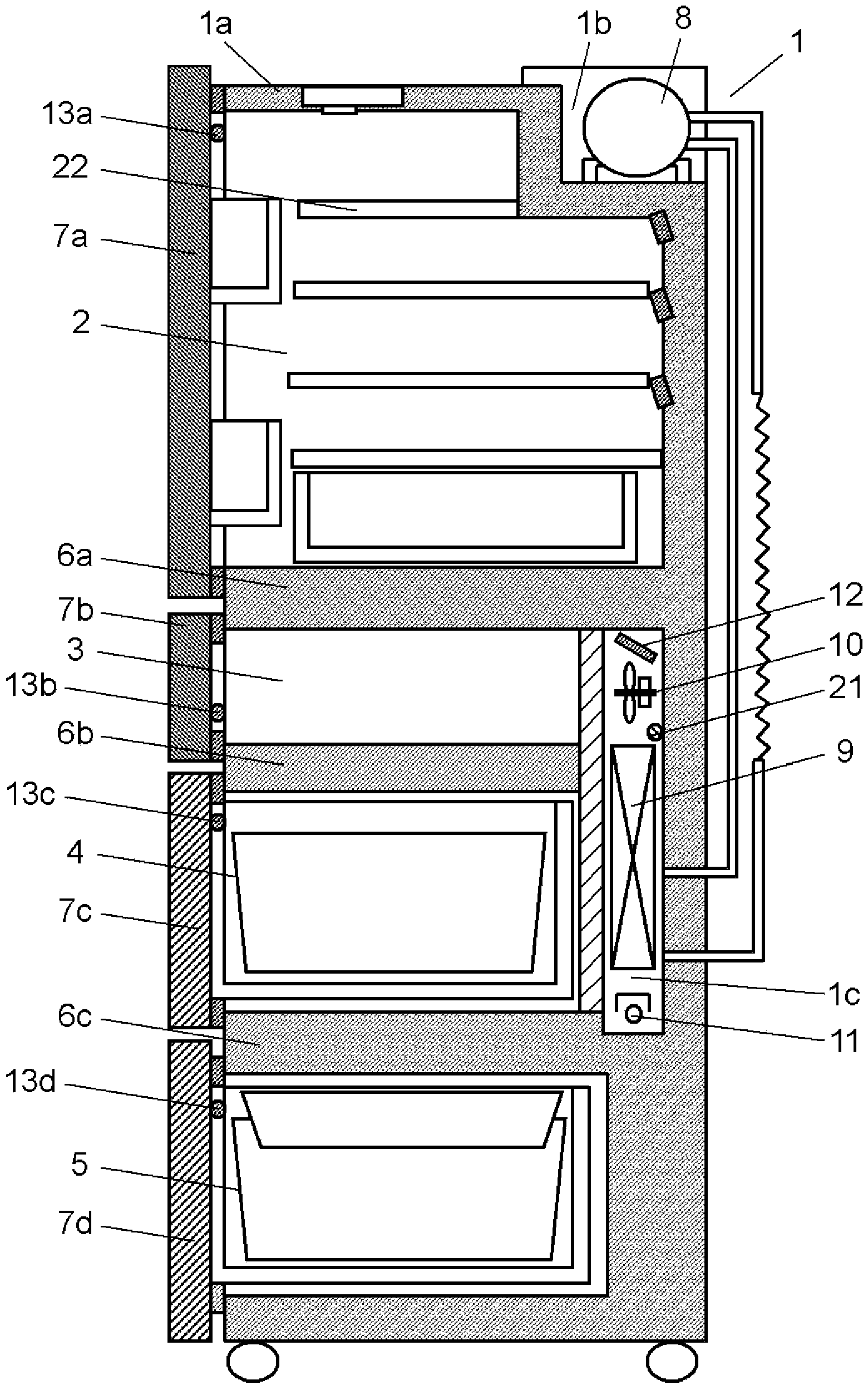
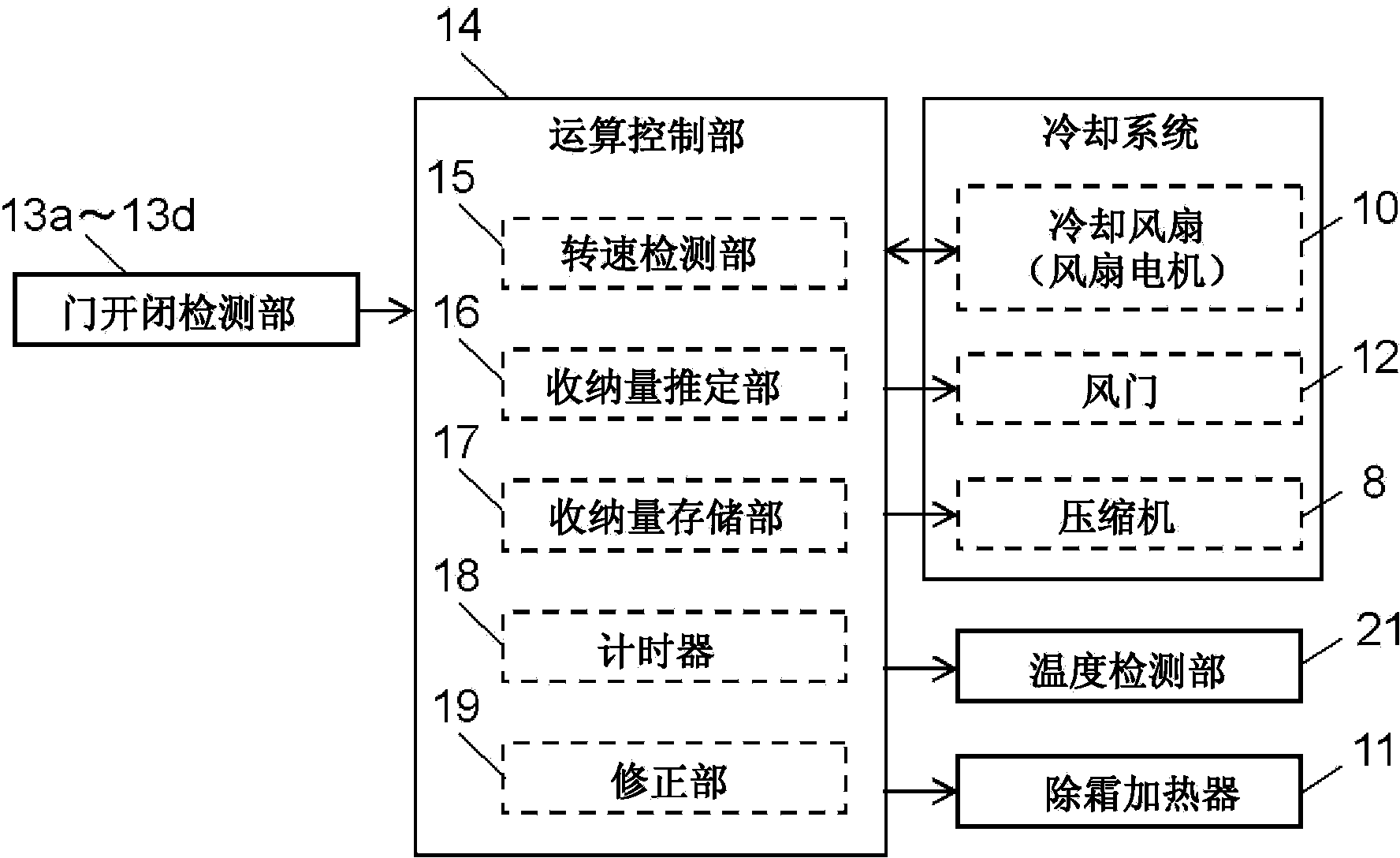
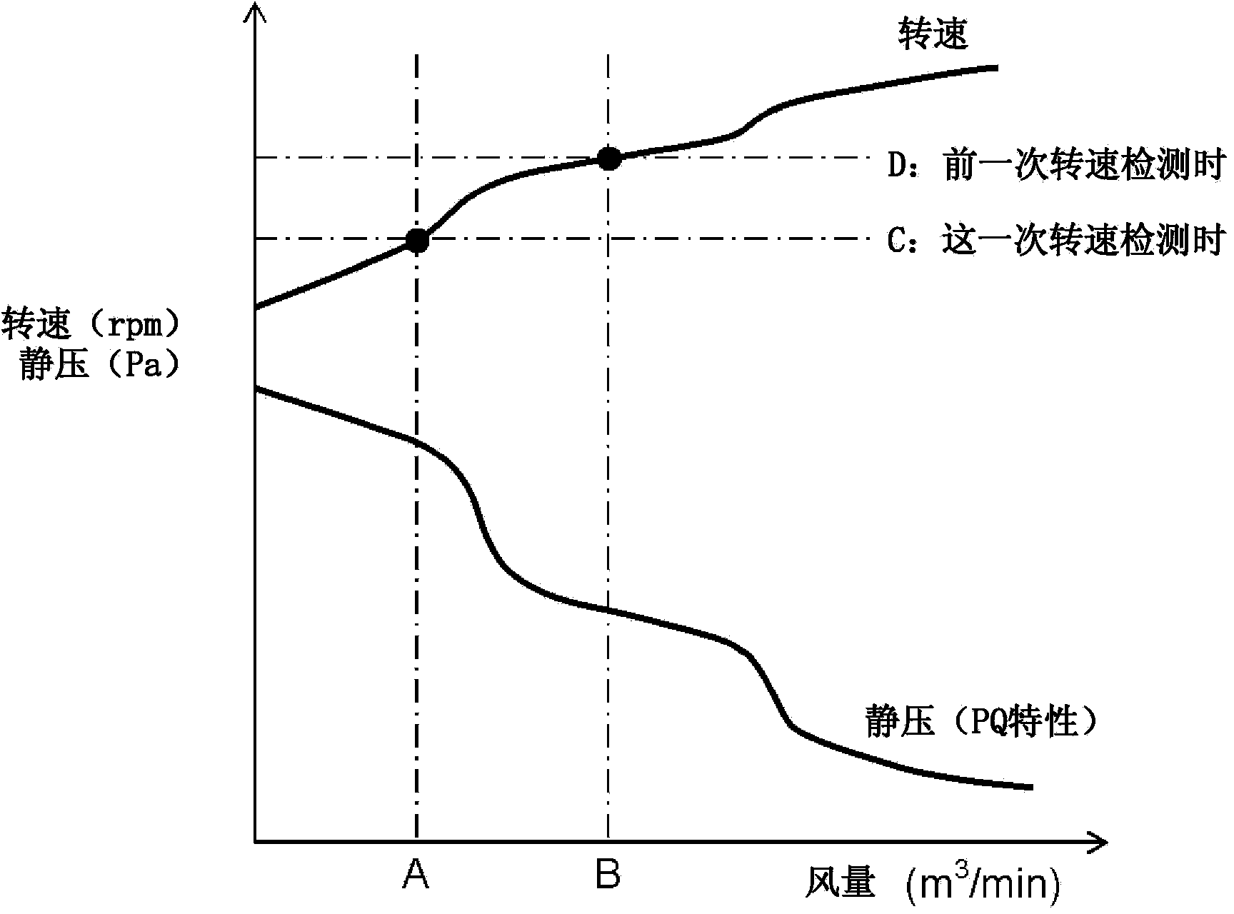
[0077] Below, according to figure 1 The first embodiment of the present invention is explained through FIG. 5 . figure 1 It is a side sectional view of the refrigerator in the first embodiment of the present invention, figure 2 It is a control block diagram of the refrigerator in 1st Embodiment of this invention. in addition, Figure 3A It is a characteristic diagram of the air volume, static pressure and rotational speed of the cooling fan of the refrigerator in the first embodiment of the present invention, Figure 3B is a characteristic diagram of the rotational speed of the cooling fan and the storage capacity of the refrigerator in the first embodiment of the present invention, Figure 4 It is a control flowchart of the refrigerator in 1st Embodiment of this invention. Figure 5A is a characteristic diagram of the air volume and rotation speed of the cooling fan including the correction factor in the refrigerator in the first embodiment of the present invention, ...
no. 2 approach
[0105] Below, according to Figure 6 The refrigerator in 2nd Embodiment of this invention is demonstrated to FIG. 9. FIG. Figure 6 is a control block diagram of the refrigerator in the second embodiment of the present invention, Figure 7A It is a characteristic diagram of the air volume, static pressure, and input current of the cooling fan of the refrigerator in the second embodiment of the present invention, Figure 7B It is a characteristic diagram of the input current to the cooling fan and the storage capacity of the refrigerator in the second embodiment of the present invention. Figure 8 is a control flowchart of the refrigerator in the second embodiment of the present invention, Figure 9A is a characteristic diagram of the air volume of the cooling fan and the input current including correction factors in the refrigerator in the second embodiment of the present invention, Figure 9B It is a characteristic diagram of the input current to the cooling fan and the st...
no. 3 approach
[0121] Below, according to Figure 10 to Figure 12 The refrigerator in 3rd Embodiment of this invention is demonstrated. Figure 10 is a control block diagram of the refrigerator in the third embodiment of the present invention, Figure 11AIt is a characteristic diagram of the air volume, static pressure and rotational speed of the cooling fan of the refrigerator in the third embodiment of the present invention, Figure 11B It is a characteristic diagram of the rotation speed of the cooling fan of the refrigerator in 3rd Embodiment of this invention, and a storage capacity. Figure 12 It is a control flowchart of the refrigerator in 3rd Embodiment of this invention. In addition, the same code|symbol is attached|subjected to the same part as 1st Embodiment or 2nd Embodiment, and description is abbreviate|omitted.
[0122] The refrigerator in the third embodiment of the present invention constituted as above is characterized in that there is no correction step (step S3 to ste...
PUM
 Abstract
Description
Claims
Application Information
 - R&D
- Intellectual Property
- Life Sciences
- Materials
- Tech Scout
- Unparalleled Data Quality
- Higher Quality Content
- 60% Fewer Hallucinations
Browse by: Latest US Patents, China's latest patents, Technical Efficacy Thesaurus, Application Domain, Technology Topic, Popular Technical Reports.
© 2025 PatSnap. All rights reserved.Legal|Privacy policy|Modern Slavery Act Transparency Statement|Sitemap|About US| Contact US: help@patsnap.com


