Method and Apparatus of Optimizing the Cooling Load of an Economized Vapor Compression System

a technology of economized vapor compression and cooling load, which is applied in the direction of refrigeration safety arrangement, refrigeration components, lighting and heating apparatus, etc., can solve the problems of inability to control the compressor to match the multi-stage compressor performs not as well as the single-stage compressor, and the compressor is unable to meet the load requirements of the economized vapor compression system, so as to reduce the speed of the compressor and reduce the efficiency rate rate of the compressor

Inactive Publication Date: 2008-11-20
CARRIER CORP
View PDF10 Cites 16 Cited by
  • Summary
  • Abstract
  • Description
  • Claims
  • Application Information

AI Technical Summary

Benefits of technology

[0007]The speed of the compressor is varied to match the cooling load requirements of the vapor compression system. The compressor includes a motor that operates the compressor at a variable speed. By adjusting the speed of the compressor, the mass flow rate of the refrigerant through the vapor compression system can be controlled to efficiently cool the refrigerated container. Increasing the speed of the compressor increases the mass flow rate of the refrigerant and the capacity of the heat accepting heat exchanger to cool the refrigerated container. Decreasing the speed of the compressor decreases the mass flow rate of the refrigerant and the capacity of the heat accepting heat exchanger to cool the refrigerated container.
[0008]The vapor compression system includes an air temperature sensor that measures an air temperature in the refrigerated container. A desired set point temperature is programmed into a microcontroller. When the air temperature sensor detects that the air temperature is above a threshold temperature, the microcontroller increases the speed of the compressor to increase the mass flow rate of the refrigerant and therefore the cooling capacity of the vapor compression system.
[0009]When the air temperature sensor detects that the air temperature is within a predetermined range from the set point temperature, the microcontroller sends a signal to slightly decrease the speed of the compressor. This allows for fine adjustment of the cooling capacity of the vapor compression system to prevent overcooling of the refrigerated container. Once the air temperature sensor detects that the air temperature equals the set point temperature, the microcontroller sends a signal to slow down the motor of the compressor to maintain the set point temperature and match the cooling load of the vapor compression system.

Problems solved by technology

A drawback to employing a multi-stage compressor is that it is expensive.
Additionally, multi-stage compressors do not perform as well as single stage compressors in certain operating conditions.
Finally, as the speed of the multi-stage compressor is fixed, the compressor is unable to be controlled to match the load requirements of the vapor compression system.

Method used


Image

  • Method and Apparatus of Optimizing the Cooling Load of an Economized Vapor Compression System
  • Method and Apparatus of Optimizing the Cooling Load of an Economized Vapor Compression System

Examples


Embodiment Construction

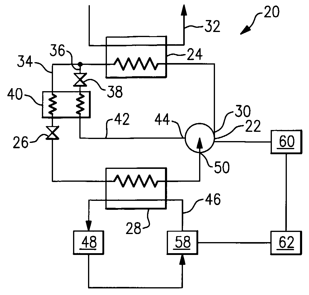
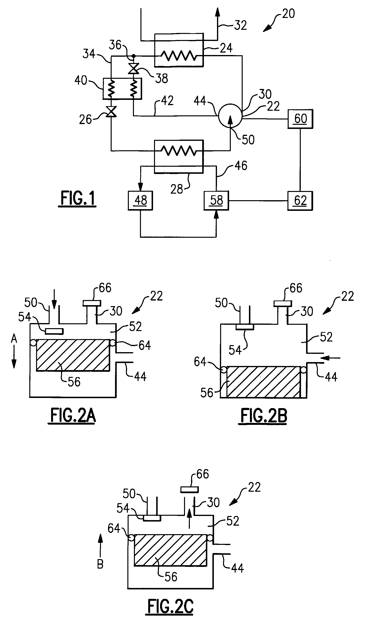
[0016]FIG. 1 illustrates an example vapor compression system 20 including a single stage compressor 22, a heat rejecting heat exchanger 24, an expansion device 26, and a heat accepting heat exchanger 28. Refrigerant circulates though the closed circuit vapor compression system 20. The refrigerant exits the compressor 22 through a discharge port 30 at a high pressure and a high enthalpy.

[0017]The refrigerant then flows through the heat rejecting heat exchanger 24, such as a condenser or gas cooler. An external fluid medium 32, such as water or air, flows through the heat rejecting heat exchanger 24 and exchanges heat with the refrigerant flowing through the heat rejecting heat exchanger 24. The refrigerant rejects heat to the external fluid medium 32 and exits the heat rejecting heat exchanger 24 at a relatively low enthalpy and a high pressure.

[0018]The refrigerant then splits into a main flow path 34 and an economizer flow path 36. Refrigerant in the economizer flow path 36 is expa...


PUM


Abstract

A vapor compression system includes a variable speed single stage compressor, a heat rejecting heat exchanger, an expansion device, and a heat accepting heat exchanger. The speed of the compressor is varied to control the refrigerant flow rate and match the cooling load requirements of the vapor compression system. A temperature sensor measures an air temperature in the refrigerated container. When the temperature sensor detects that the air temperature is above a threshold temperature, the microcontroller increases the speed of the compressor to increase the refrigerant flow rate and the cooling capacity of the vapor compression system. When the air temperature sensor detects that the air temperature is within a predetermined range from the set point temperature, the microcontroller sends a signal to slightly decrease the speed of the compressor, allowing fine adjustment of the cooling capacity of the vapor compression system to prevent overcooling of the refrigerated container.

Description

BACKGROUND OF THE INVENTION[0001]The present invention relates generally to a method of optimizing the cooling load of an economized vapor compression system by varying a speed of a single stage compressor.[0002]A vapor compression system includes a compressor, a heat rejecting heat exchanger, an expansion device, and a heat accepting heat exchanger. Refrigerant circulates though the closed circuit system. The refrigerant exits the compressor through a discharge port at a high pressure and a high enthalpy. The refrigerant then flows through the heat rejecting heat exchanger at a high pressure and rejects heat to an external fluid medium. The refrigerant then flows through the expansion device, which expands the refrigerant to a low pressure. After expansion, the refrigerant flows through the heat accepting heat exchanger and absorbs heat from an air stream to cool a refrigerated container. The refrigerant then re-enters the compressor through a suction port, completing the cycle.[00...

Claims


Application Information

Patent Timeline
Patent Type & Authority Applications(United States)
IPC IPC(8): F25B49/00
CPCF25B1/10F25B49/025F25B2400/13F25B2600/0253F25B2700/2104F25B2700/21172F25B2700/21173Y02B30/741Y02B30/70
Inventor BEAGLE, WAYNE P.
Owner CARRIER CORP
Why Eureka
Try Eureka