Eureka AIR delivers breakthrough ideas for toughest innovation challenges, trusted by R&D personnel around the world.

Piezoelectric actuator and method of producing the same

Inactive Publication Date: 2007-11-08
DENSO CORP
View PDF1 Cites 8 Cited by
  • Summary
  • Abstract
  • Description
  • Claims
  • Application Information

AI Technical Summary

Benefits of technology

[0011] Unlike the conventional sleeve having a one-piece unitary structure adapted to be fitted around the piezoelectric device by insertion of the piezoelectric device into the sleeve, the sleeve of the present invention has a split structure composed of a plurality of circumferentially separated sleeve segments that can be mated or assembled together into a substantially cylindrical shape provided on and around the outer circumferential surface of the piezoelectric device. In the manufacture of the piezoelectric actuator, positioning of the sleeve segments in a circumferential direction can be easily achieved so that the sleeve can be formed with high accuracy.
[0035] Furthermore, it is preferable that the molding resin is a silicone resin, epoxy resin, polyimide resin, or polyurethane resin. By using one of these materials, it is possible for the molding resin to insure accurate and reliable formation of a sleeve on the outer circumferential surface of the piezoelectric device and also provide a sufficient electric insulation between the piezoelectric device and the case. Other materials may be used for the molding resin where appropriate.

Problems solved by technology

In this instance, however, since the molding resin applied to the outer peripheral surface of the piezoelectric device is brought into contact with the sleeve, it is difficult for the molding resin to maintain the homogeneity thereof.
For instance, if the amount of molding resin applied to the piezoelectric device is excessively large, the molding resin will be squeezed out from the sleeve, requiring a separate work or process for removing the squeeze-out of the molding resin.
However, due to an extremely narrow space formed between the piezoelectric device and the case, the filler injecting operation is very difficult to achieve and hence lowers the productivity of the piezoelectric actuator.

Method used


Image

  • Piezoelectric actuator and method of producing the same
  • Piezoelectric actuator and method of producing the same
  • Piezoelectric actuator and method of producing the same

Examples


Embodiment Construction

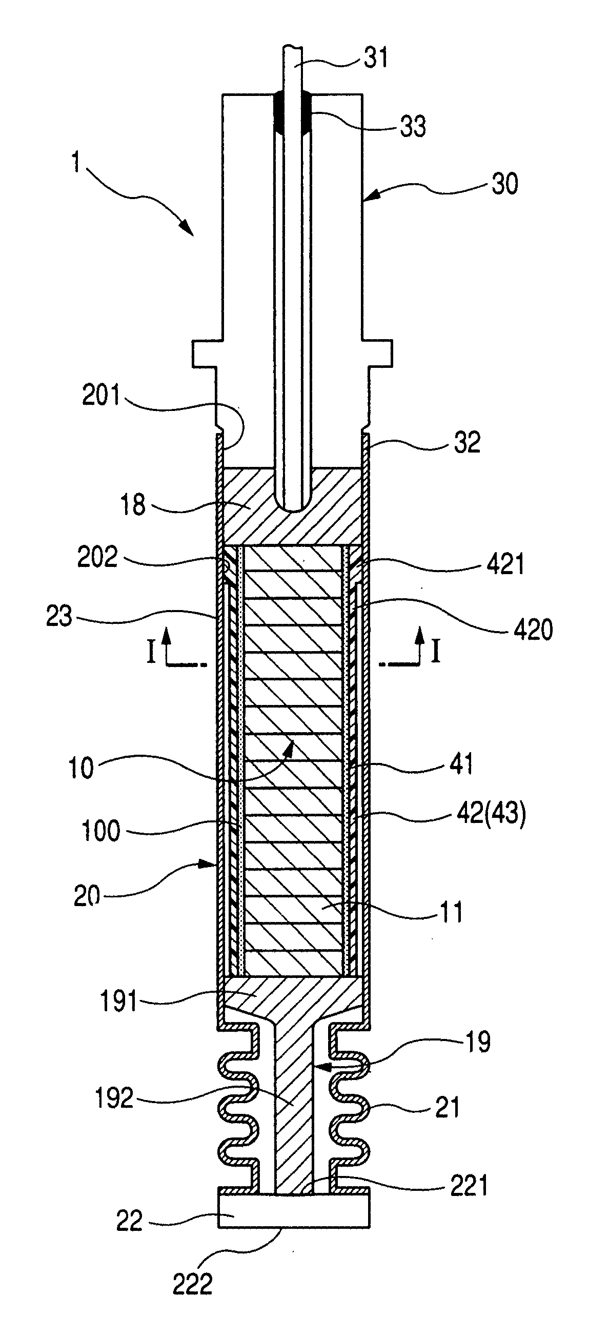
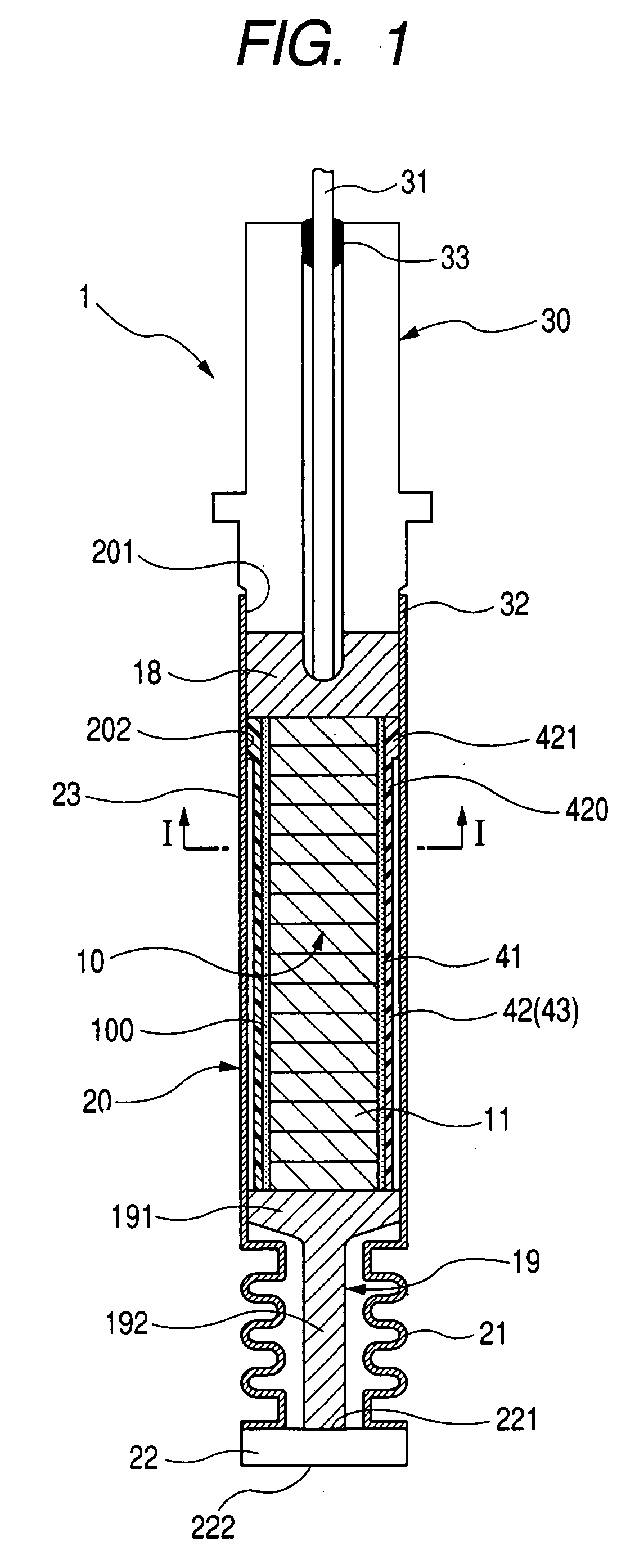
[0061] A piezoelectric actuator and a method of producing the same will be described below with reference to a first embodiment shown in FIGS. 1 through 10. As shown in FIG. 1, the piezoelectric actuator 1 according to the first embodiment of the present invention generally comprises a case 20 having a bottomed cylindrical shape including an extendable and contractible portion 21 formed at least at a part of the cylindrical case 20 in an axial direction thereof, a stacked actuator device 10 received or housed in the cylindrical case 20, and a housing 30 provided with a pair of external electrodes 31 for power supply to the piezoelectric actuator 1 and connected to an open end 201 of the cylindrical case 20.

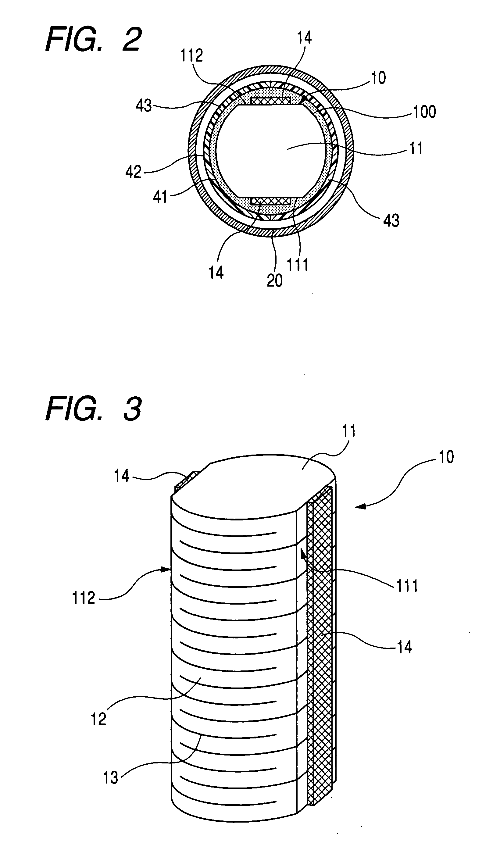
[0062] As shown in FIGS. 1 and 2, between the piezoelectric device 10 and the cylindrical case 20, a molding resin 41 having an electric insulation property is provided on an outer circumferential surface 100 of the piezoelectric device 10 and a sleeve 42 having an electric insul...


PUM


Abstract

A piezoelectric actuator includes a stacked piezoelectric device received in a cylindrical case having an extendable and contractible portion formed at least at an axial part thereof, and a housing provided with a pair of external electrodes for power supply and connected to an open end of the cylindrical case. Between the piezoelectric device and the cylindrical case, a molding resin having an electric insulation property is provided on an outer circumferential surface of the piezoelectric device, and a sleeve having an electric insulation property is provided on the molding resin. The sleeve is formed by a plurality of circumferentially separated sleeve segments assembled together into a substantially cylindrical shape.

Description

CROSS REFERENCE TO RELATED APPLICATION [0001] The present application is based on and claims priority from Japanese Patent Application 2006-106762, filed April 7, 2006, the contents of which are incorporated herein by reference. BACKGROUND OF THE INVENTION [0002] 1. Field of the Invention [0003] The present invention relates to a piezoelectric actuator having a piezoelectric device received in a case and a method of producing the piezoelectric actuator. [0004] 2. Description of the Related Art [0005] Piezoelectric actuators for used in a fuel injector of an internal combustion engine of an automobile or the like are known heretofore, which comprise a piezoelectric device drivable upon application of an electric voltage is received in a tightly-sealed fashion within a case having an extendable and contractible portion in the form of a metal bellows. One example of such known piezoelectric actuators is disclosed in Japanese Patent Laid-open Publication (JP-A) No. 2002-256999, which co...

Claims


Application Information

Patent Timeline
IPC IPC(8): H01L41/083F02M51/00F02M51/06H01L41/187H01L41/22H01L41/23H02N2/00
CPCF02M2200/21H01L41/0833H01L41/053H01L41/23H10N30/883H10N30/88H10N30/503H10N30/02
Inventor BUMA, KANEO
Owner DENSO CORP
Why Eureka
Eureka Blog
Learn More