
Proof printing adjustment system and method

a technology of adjustment system and proof printing, which is applied in the direction of instruments, digital computers, computing, etc., can solve the problems of not always matching the colors printed by high-volume output devices, not cost-effectively printing proofs using high-volume output devices, and high-volume output devices to print images

Inactive Publication Date: 2007-11-08
EASTMAN KODAK CO
View PDF13 Cites 20 Cited by
  • Summary
  • Abstract
  • Description
  • Claims
  • Application Information

AI Technical Summary

Benefits of technology

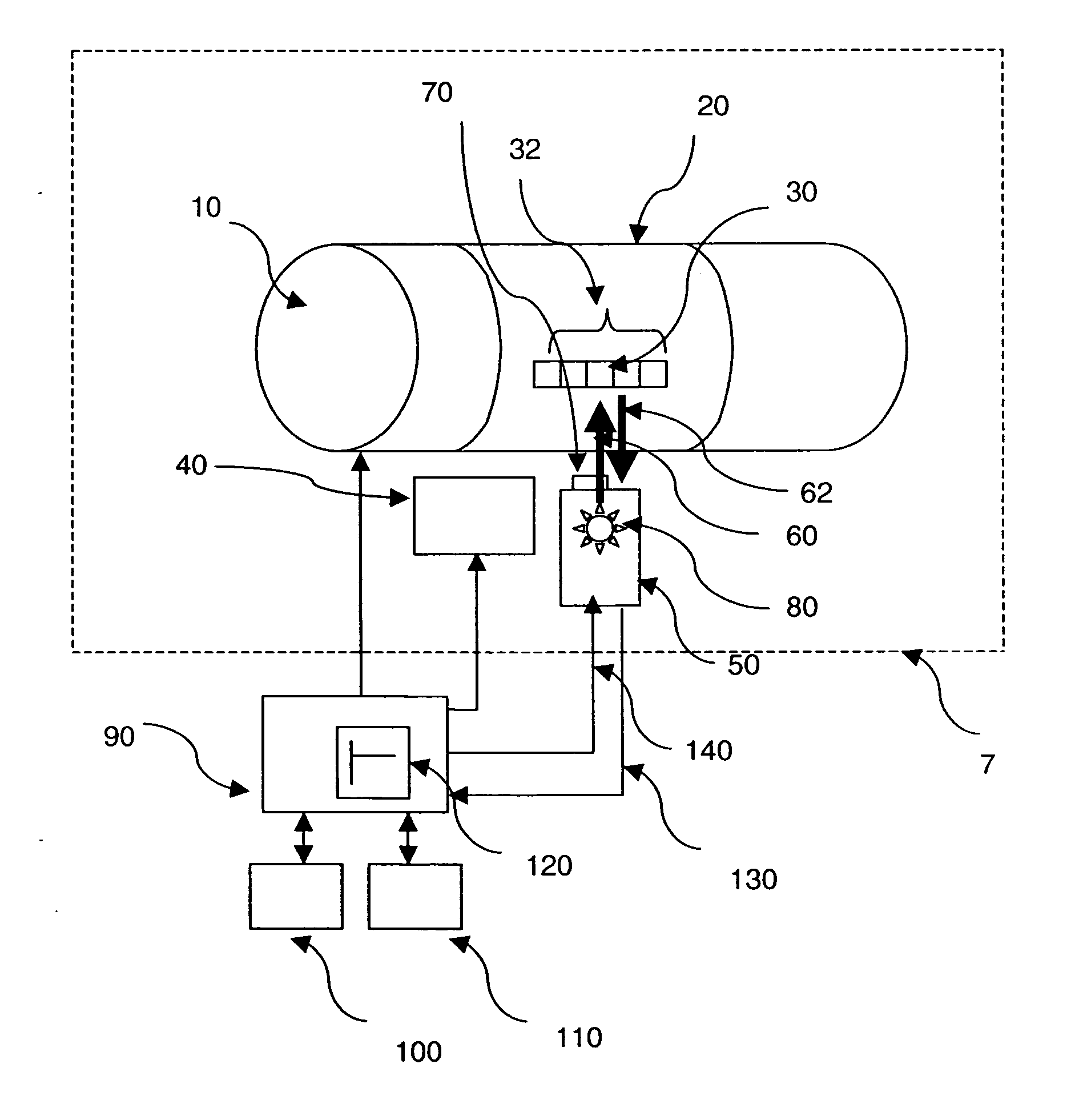
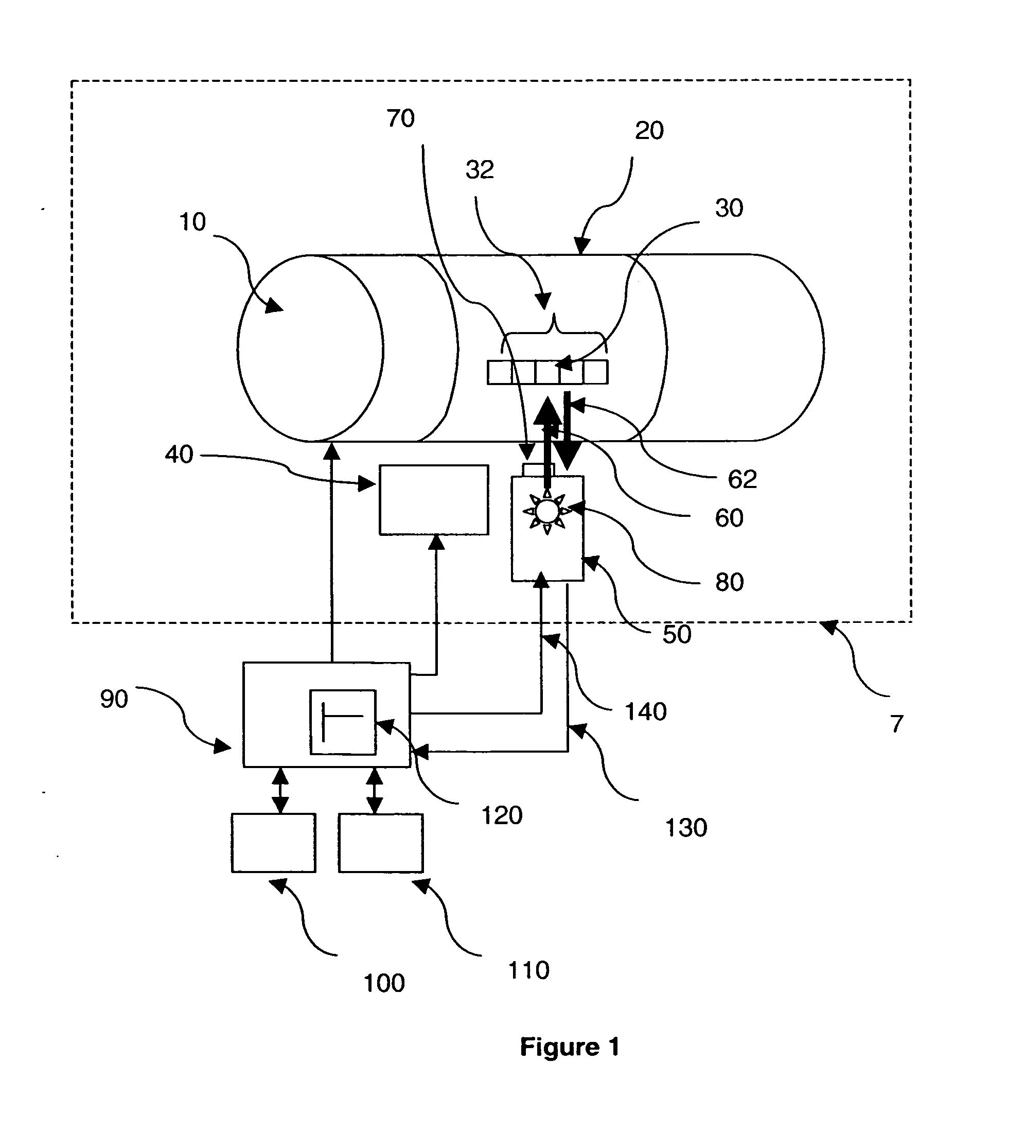
[0012] The present invention provides a system and method to reduce the time to measure a color in a proof printing system by using a spectrophotometer integrated with a printer. In one embodiment, an ink color patch is printed on a substrate (which may be, for example, paper or other material suitable for printing on), the color patch is illuminated with light from the spectrophotometer (when the substrate is still located on the printer), light that is reflected off the color patch is collected by the spectrophotometer, an output signal is generated by the spectrophotometer (which is based on collected light reflected by the color patch) which is input to a controller. The controller is coupled to the spectrophotometer, a temperature measurement device, a humidity measurement device, a support surface (such as, for example, a platen moving in X-Y, a platen moving in Y with a print head moving in X, and / or the like) and a print head. The controller uses the output signal from the spectrophotometer, the humidity measurement and temperature measurement to access its preprogrammed internal color adjustment dry-rate lookup table (which may contain, such as, for example, the spectrophotometer model, printer model, paper type, ink type, temperature, humidity and the like which point to, such as, for example, a color profile, a color profile with different colors of backing material, a color profile with an ultraviolet (UV) filter, a color profile without the UV filter, a color profile based on different standards, and the like) to adjust the present spectrophotometer output signal to that of what it would be at a goal color. In other words, since the presently measured color will result in the goal color, the spectrophotometer output is adjusted to what it would be at the goal color. As a consequence, a user does not need to wait to see if the goal color results since the presently measured color has been pre-determined to result in the goal color.
[0018] The present invention may also provide for the output signal to be adjusted to compensate for a color of the background against which the printing substrate is positioned at the time of measurement of the color patch and also to compensate for the presence or absence of ultraviolet illumination in the illuminating light of the spectrophotometer. The present invention may also allow for the output of the spectrophotometer to be adjusted based on an internal color standard that is calibrated against a reference color standard.
[0021] In a further embodiment of the present invention, the spectrophotometer output signal is used to compute how a human observer would perceive the color patch; then the numeric representation of human perceived color is fed back into an algorithm within the controller and compared to that of a reference standard against a tolerance in order to render a pass / fail judgment. Typically, a sticker is placed on a printed page in order to indicate its quality level. With the present invention, the system can automatically print such label directly on the printed substrate without user intervention, using the adjusted spectrophotometer output signal along with suitable computer algorithms contained in the controller. The system is therefore able to perform color measurement, calibration, and confirmation without human intervention.

Problems solved by technology

It is not, however, cost effective to print the proof using high volume output devices of the type used to print large quantities of the image.
This is because it is expensive to set up high volume output devices to print the image.
In practice, it has been found that colors printed by digital color printers do not always match colors printed by high volume output devices.
Therefore, a proof printed by the digital color printer may not have colors that match the colors printed by the high volume output device.
The use of such stand-alone spectrophotometers for proofing is very costly.
Part of this cost is created by the inherent redundancy of many of the systems used in those devices.
Thus, the total cost of the proofing system, including a separate stand-alone spectrophotometer and a proofer, is very high.
Installation and maintenance costs are also high because two separate devices, typically manufactured by different vendors, must be separately purchased, installed, and maintained.
Various makes and models of spectrophotometers are used for color management and, since there is significant measurement bias between devices, considerable measurement variability results.
Finally, there is a significant labor cost associated with making calibration and color management adjustments to the proofer using a stand-alone spectrophotometer.
Accordingly, there are substantial cost and efficiency penalties associated with stand-alone proofing combinations.

Method used


Image

  • Proof printing adjustment system and method
  • Proof printing adjustment system and method

Examples


Embodiment Construction

[0025] Referring to FIG. 1, a proof printing system 5 of the present invention is illustrated. System 5 includes a printer 7, a controller 90 coupled to the printer 7, a humidity sensor 100 coupled to the controller 90 and a temperature sensor 110 coupled to the controller 90. Printer 7 is preferably a commercial printer and has a spectrophotometer 50 integrated with it. Drum 10 is internal to printer 7. Drum 10 and a print head 40 are coupled to the controller 90. The spectrophotometer 50, which contains an illumination source 80, is coupled to the controller 90. An ultraviolet (UV) filter 70 is coupled to the spectrophotometer 50. A substrate 20 is coupled to the drum 10 and a color target 32 containing color patch 30 (which is one of one or more color patches that form color target 32) is printed on substrate 20. Drum 10 is preferably a printer drum; however, it may also be a platen or any other suitable type of printing support surface.

[0026] In operation, the print head 40 pri...


PUM


Abstract

A proof printing system and method comprises a printer and supporting firmware for the printer, the printer comprising spectrophotometer integrated with the printer, which printer may be a commercial printer. The supporting firmware comprises color adjustment tables an / or algorithms. The system is capable of color confirmation and color calibration. The proof printing system is capable of adjusting the output signal of the spectrophotometer to compensate for conditions at the time of printing or conditions at the time of spectrophotometric measurement. The system is also capable of predicting the time it takes a color patch to reach a predetermined degree of drying that will allow reliable spectrophotometric measurements to be made. Measurement and printing conditions compensated for include at least drying of the ink, based on the determination of at least one of humidity and temperature. Measurement conditions additionally compensated for include the use of different colors of backing behind the proof and the presence or absence of an ultraviolet cutoff filter. The proof printing system can also adjust the output signal of the spectrophotometer based on a reference color standard.

Description

FIELD OF THE INVENTION [0001] The present invention relates to a proof printing adjustment system and method. In particular, the present invention relates to a system and method to reduce the time to measure a color in a proof printing system. BACKGROUND OF THE INVENTION [0002] It is common to provide a sample of an image to a customer for approval prior to printing a large number of copies of an image using a high volume output device such as a printing press. The sample image is known as a “proof”. The proof is used to ensure that the consumer is satisfied with, among other things, a color of the image. [0003] It is not, however, cost effective to print the proof using high volume output devices of the type used to print large quantities of the image. This is because it is expensive to set up high volume output devices to print the image. Accordingly, it has become a practice in the printing industry to use digital color printers to print proofs. Digital color printers render colo...

Claims


Application Information

Patent Timeline
Patent Type & Authority Applications(United States)
IPC IPC(8): G06F15/00
CPCH04N1/6091H04N1/6055H04N1/6044
Inventor BIELAK, RICHARD R.CANONAYON, JENNIFER LASKIN
Owner EASTMAN KODAK CO
Learn More