Network profiling system having physical layer test system

a network profiling and physical layer technology, applied in the field of wireless communication, can solve the problems of low rf, high interference at the input to the base station receiver, and the potential disruption of the existing radio link between the base station and the mobile phone of customers

Inactive Publication Date: 2007-11-08
SUNRISE TELECOM
View PDF17 Cites 157 Cited by
  • Summary
  • Abstract
  • Description
  • Claims
  • Application Information

AI Technical Summary

Problems solved by technology

Transmission of very low RF power indicates problems with the antenna or the cabling between the antenna transmitter, receiver, and the cellular base station, known as the backhaul.
However, if a “live” (i.e., currently in-use) test is required, the injected signal has the potential to disrupt the existing radio links between the base station and customers' mobile phones.
For example, when testing a receive antenna (i.e., an antenna operating at the base station receive frequencies), as the network analyzer's source sweeps through the channel that the mobile phone's transmitter occupies (i.e., up-link channel from the mobile phone to the base station), a high level of interference is experienced at the input to the base station receiver.
The interference could result in a reduction of the call quality, and possibly cause the call to drop.
Conventional backhaul test solutions are separate systems and do not cooperate with cellular test systems.
Test data may be gathered and interpreted by a separate database and software often resulting in additional problems such as incomplete or inaccurate performance analysis and database incompatibilities to name a few.
These problems create obstacles for delivering OAMP.
Solutions to these problems have been long sought but prior developments have not taught or suggested any solutions and, thus, solutions to these problems have long eluded those skilled in the art.

Method used

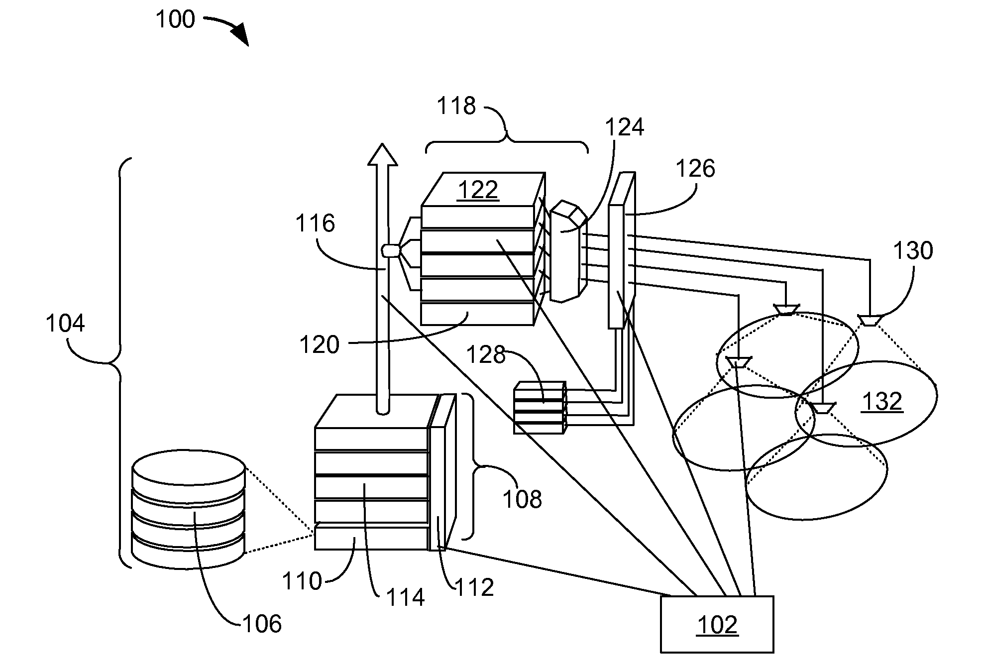
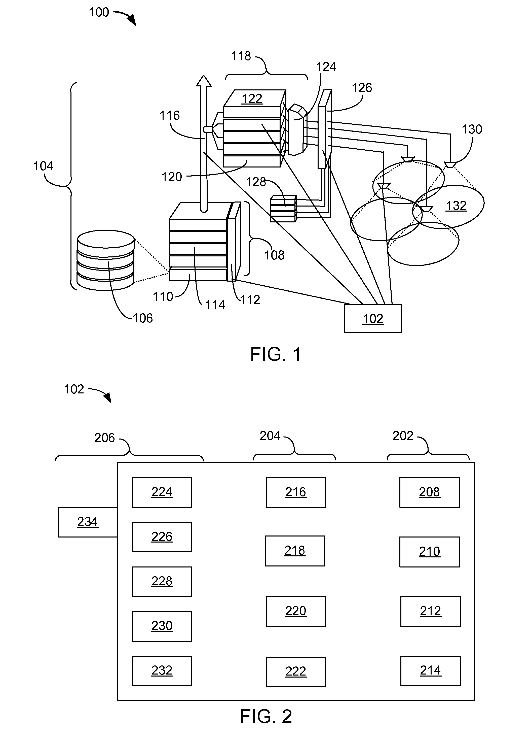
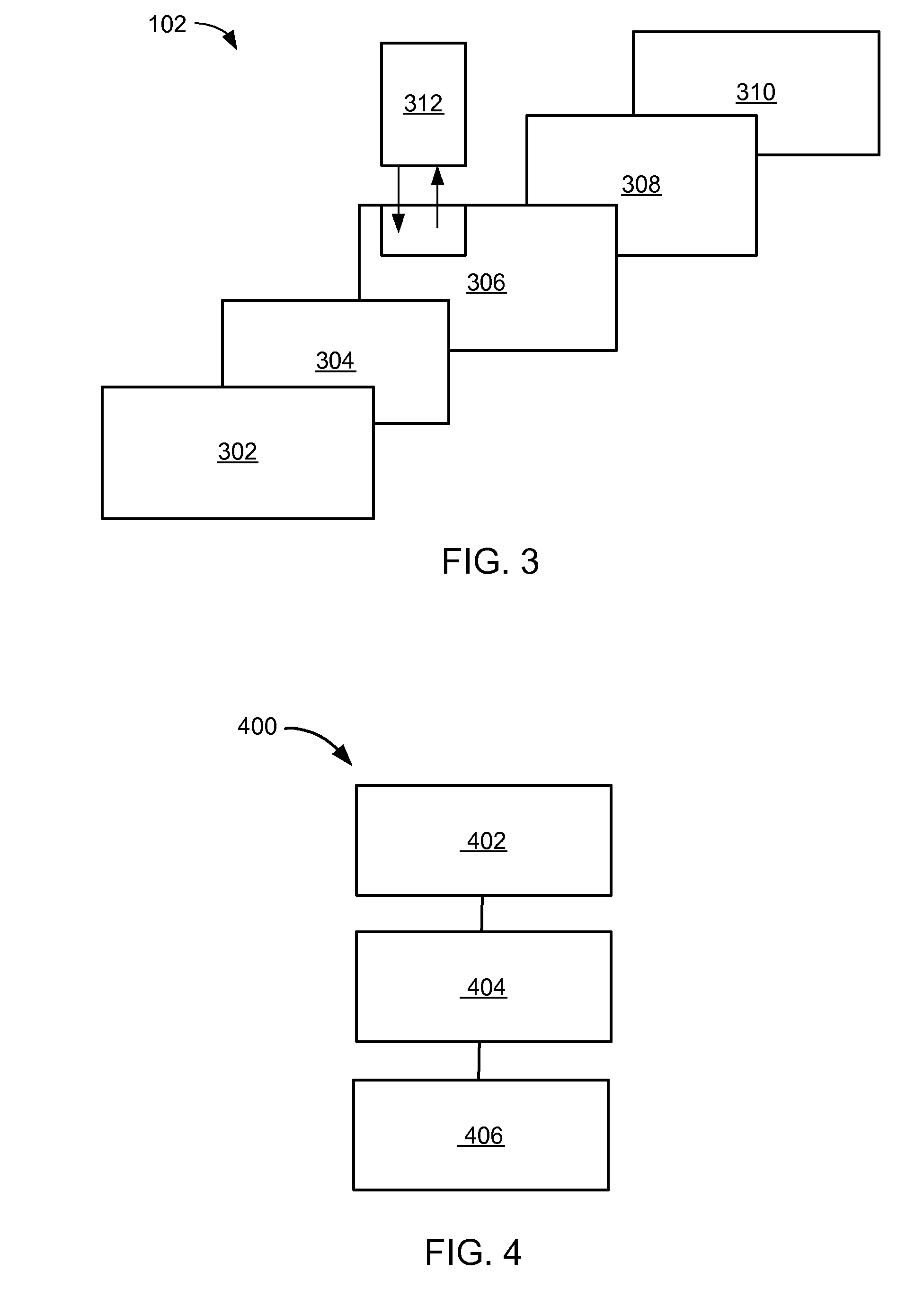

Image

  • Network profiling system having physical layer test system
  • Network profiling system having physical layer test system
  • Network profiling system having physical layer test system

Examples


Embodiment Construction

[0019]The following embodiments are described in sufficient detail to enable those skilled in the art to make and use the invention. It is to be understood that other embodiments would be evident based on the present disclosure, and that system, process, or mechanical changes may be made without departing from the scope of the present invention.

[0020]In the following description, numerous specific details are given to provide a thorough understanding of the invention. However, it will be apparent that the invention may be practiced without these specific details. In order to avoid obscuring the present invention, some well-known circuits, system configurations, and process steps are not disclosed in detail. Likewise, the drawings showing embodiments of the apparatus / device are semi-diagrammatic and not to scale and, particularly, some of the dimensions are for the clarity of presentation and are shown greatly exaggerated in the drawing FIGs.

[0021]In addition, where multiple embodime...


PUM


Abstract

A network profiling system is provided including providing a base station tester having both a spectrum analyzer and a vector network analyzer, inserting an optical time domain reflectometer system in the base station tester, and operating a touch screen display of the base station tester for testing a cellular base station having both a non-optical portion and a backhaul with an optical fiber. The operating of the touch screen display further includes testing the non-optical portion with the vector network analyzer, the spectrum analyzer, or a combination thereof. The operating of the touch screen display also includes testing the backhaul having the optical fiber with the optical time domain reflectometer system, and analyzing test data from the testing the non-optical portion with the backhaul.

Description

CROSS-REFERENCE TO RELATED APPLICATIONS[0001]This application claims the benefit of U.S. Provisional Patent Application Ser. No. 60 / 746,766 filed May 8, 2006.[0002]The present application contains subject matter related to a co-pending U.S. patent application Ser. No. 11 / 382,479. The related application is assigned to Sunrise Telecom Incorporated.[0003]The present application also contains subject matter related to a concurrently filed U.S. patent application by Michael Tolaio entitled “Network Profiling System Having Nonphysical Layer Test System”. The related application is assigned to Sunrise Telecom Incorporated and is identified by docket number 21-030.TECHNICAL FIELD[0004]The present invention relates generally to wireless communication and more particularly to a system for testing cellular base stations.BACKGROUND ART[0005]Telecommunications equipment traditionally has been offered with a significant number of features allowing on-line system test and operational maintenance ...

Claims


Application Information

Patent Timeline
Patent Type & Authority Applications(United States)
IPC IPC(8): H04J3/16
CPCH04L12/2697H04W24/06H04L43/50
Inventor TOLAIO, MICHAEL
Owner SUNRISE TELECOM
Why Eureka
Try Eureka