Method and apparatus for rifling a firearm barrel

a firearm and barrel technology, applied in the direction of process and machine control, process control, instruments, etc., can solve the problems of requiring a high level of skill to make and maintain the tooling, the problem of requiring a large amount of time and is therefore quite costly

Inactive Publication Date: 2007-11-08
BARTLEIN TRACY M +2
View PDF8 Cites 5 Cited by
  • Summary
  • Abstract
  • Description
  • Claims
  • Application Information

AI Technical Summary

Benefits of technology

[0010] The present invention is a computer controlled single point cut rifling apparatus. The apparatus includes a frame, CPU, a controller, a linear motion control servo, a rotational motion control servo unit, a feed unit, a graphical user interface and a chuck box to hold a barrel.
[0011] The CPU is preprogrammed to run a program to control the apparatus. The graphical user interface is adapted to allow the operator to run a calibration program and a set up program through which operating parameters are entered into the program on the CPU. The calibration program records the location and length of the barrel. The set up program allo

Problems solved by technology

The single point method produces very low stress on the barrel and is the most accurate method of rifling; however it takes a lot of time and is therefore quite costly.
Very few single point cut rifling machines exist, and those which do exist are old and expensive to maintain.
Furthermore, it takes a high level of skill to make and maintain the tooling, as well as the machine.
It is difficult to accommodate customer specifications on the old machines.
This can be quite difficult and time consuming.
Furthermore, the machine operator needs to be present to stop the machine when the desired number

Method used


Image

  • Method and apparatus for rifling a firearm barrel
  • Method and apparatus for rifling a firearm barrel
  • Method and apparatus for rifling a firearm barrel

Examples


Embodiment Construction

[0030] Although the disclosure hereof is detailed and exact to enable those skilled in the art to practice the invention, the physical embodiments herein disclosed merely exemplify the invention which may be embodied in other specific structures. While the preferred embodiment has been described, the details may be changed without departing from the invention, which is defined by the claims.

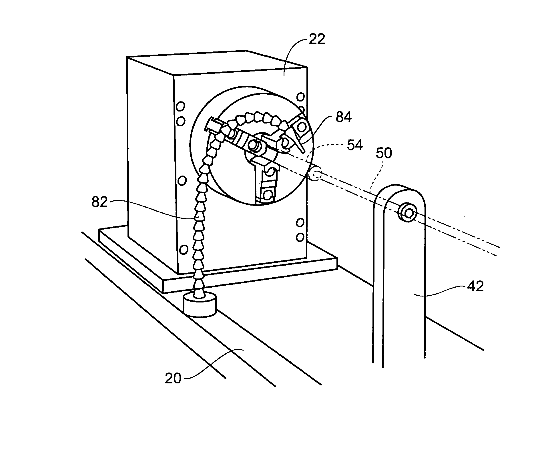
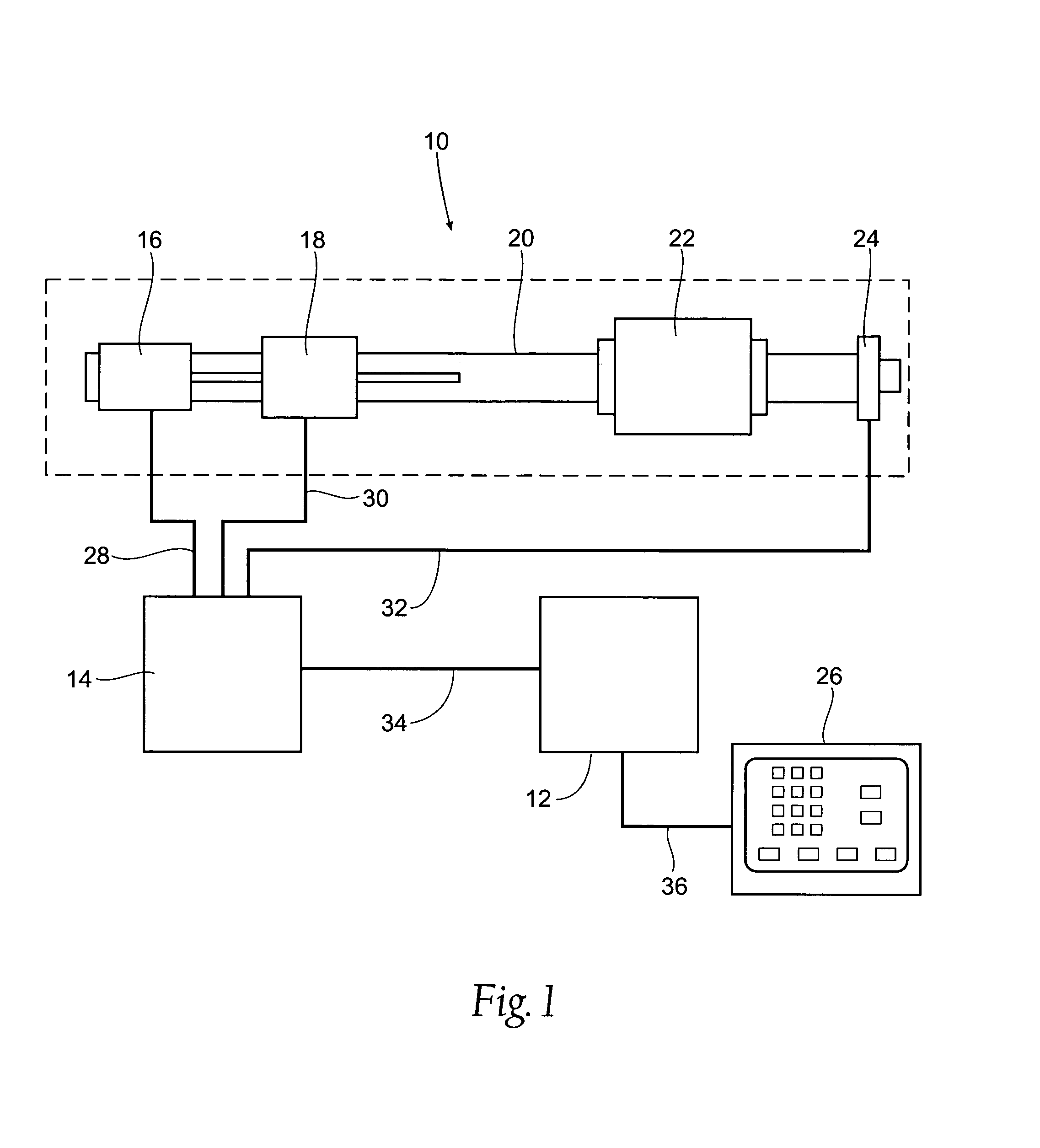
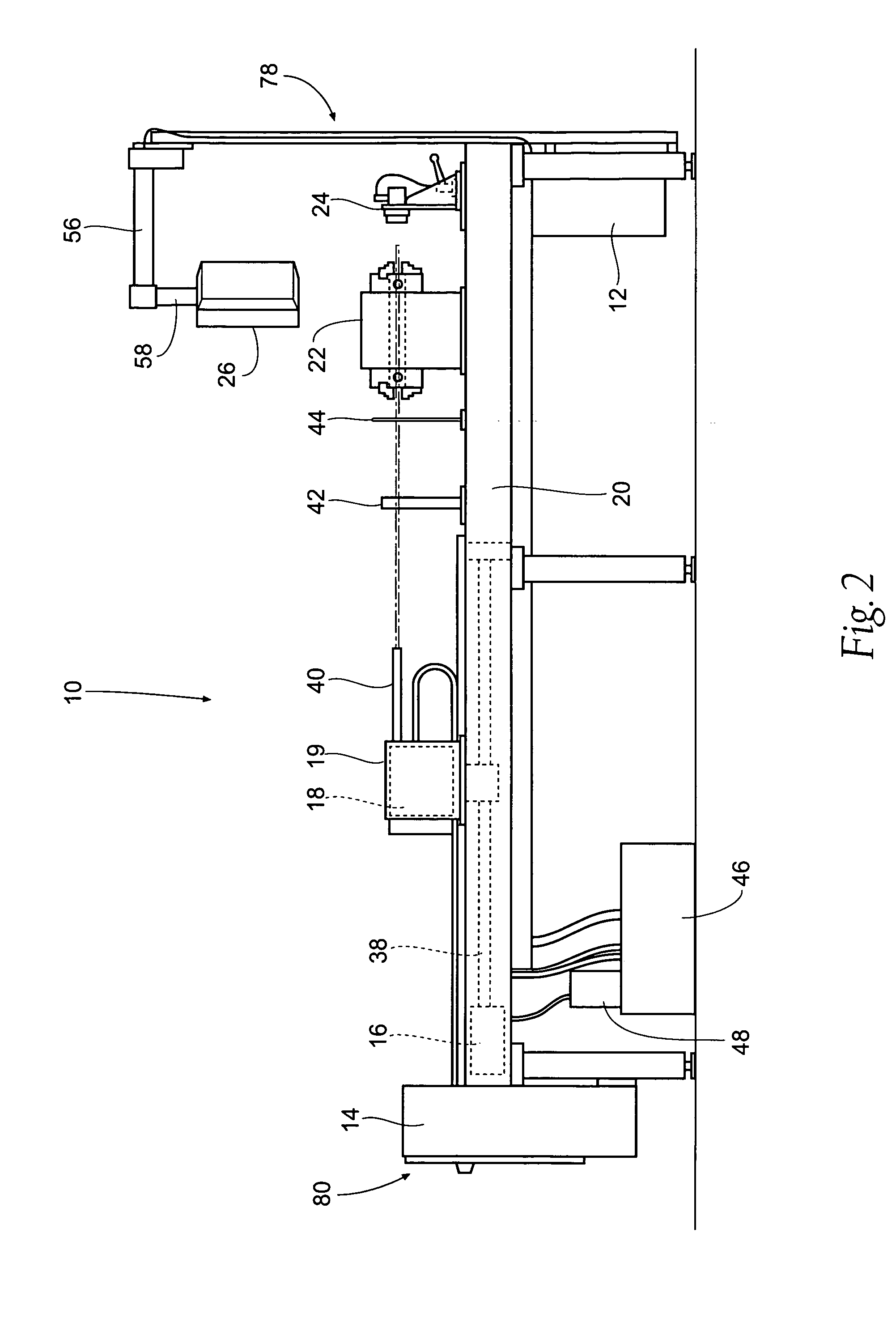
[0031]FIG. 1 shows a simplified view of a rifling machine 10 according to the present invention. The computer numerically controlled rifling machine includes a computer (CPU) 12, a controller 14, a linear motion control servo 16, a rotational motion control servo 18, a frame 20, a chuck box 22, a feed block assembly 24, and a graphical user interface (GUI) 26.

[0032] The rifling machine consists of a frame 20, to which the linear motion control servo 16, the rotational motion control servo 18, the chuck box 22, and the feed block assembly 24 are mounted.

[0033] The CPU 12 is connected to the con...


PUM

PropertyMeasurementUnit
Depthaaaaaaaaaa

Abstract

A computer numerically controlled apparatus is provided for rifling a gun barrel. The apparatus automates the known method of rifling a gun barrel. The apparatus includes a frame, a rod, a cutting tool, a rod holder, and a system of servos to move the rod holder and to rotate the rod. The apparatus includes a CPU runs a program which controls the servos based on operating parameters entered by the operator. The operating parameters are entered through a graphical user interface which also allows the operator to monitor the status of the rifling process. The operator can calibrate the system and enter the twist rate, number of grooves, cut degree, cutting speed, return speed, and number of passes to complete. The apparatus includes a puck which engages the end of the rod and is adapted to index the rod and change the cutting depth of the cutting tool.

Description

BACKGROUND OF THE INVENTION [0001] Many firearms have a rifled barrel. The rifling consists of spiral grooves which are cut or formed into the inner surface of the barrel of a gun. The spiral grooves impart spin to the bullet. This spin creates gyroscopic forces which stabilize the bullet and increase its accuracy. [0002] The most common methods of rifling a barrel include single point cut, broach cut, button rifling, and hammer forge rifling. Each method of rifling has advantages and disadvantages. [0003] Single point cut rifling is the oldest method of rifling still in use today. In this method a cutter hook is attached to the end of a rod. The rod is rotated and pulled through the bore in the barrel blank. The hook removes a small amount of material with each pass. After cutting the first shallow groove, the tool is indexed to cut the next shallow groove. After all the shallow grooves have been cut to the same depth, the hook tool is adjusted to take a deeper cut. This process is...

Claims


Application Information

Patent Timeline
IPC IPC(8): B23D37/00
CPCB23D5/02G05B2219/35312Y10T409/40315Y10T409/400175G05B2219/35488
Inventor BARTLEIN, TRACY M.KIHN, ANDREW F.DAYWALT, KEVIN L.
Owner BARTLEIN TRACY M
Why Eureka
Try Eureka