Electrical-tap connector

a technology of electrical tape connectors and connectors, which is applied in the direction of coupling contact members, coupling device connections, contact members penetrating/cutting insulation/cable strands, etc., can solve the problems of reducing the reliability of u-shaped terminals, and achieve the effect of maximizing current-carrying capacity and increasing terminal li

Inactive Publication Date: 2007-11-08
KS TERMINALS INC
View PDF16 Cites 6 Cited by
  • Summary
  • Abstract
  • Description
  • Claims
  • Application Information

AI Technical Summary

Benefits of technology

[0011] Meanwhile, a pair of mating dovetail-joint is positioned on the bilateral sides of the insulated housing for providing one type of configuration, so that multiple terminals may easily be paralleled facilitate the terminal for broader usage.
[0012] By providing a unique configuration of a generally W-shaped terminal for receiving a blade contact, the design according to the spirits of the present invention increases the lifetime of the terminal and allows the contact interface between the terminal and the blade contact to extend to the maximum, thus maximize the current-carrying capacity.

Problems solved by technology

Although the configuration of the generally U-shaped terminal provides the maximum current-carrying capacity of the terminal, the design of the offset portion (46, 46a, 46b) provides an uneven contact while the blade contact (14) is in mating engagement with the offset portion (46) of the blade-receiving terminal (22), thus reducing the reliability of the U-shaped terminal.

Method used


Image

  • Electrical-tap connector
  • Electrical-tap connector
  • Electrical-tap connector

Examples


Embodiment Construction

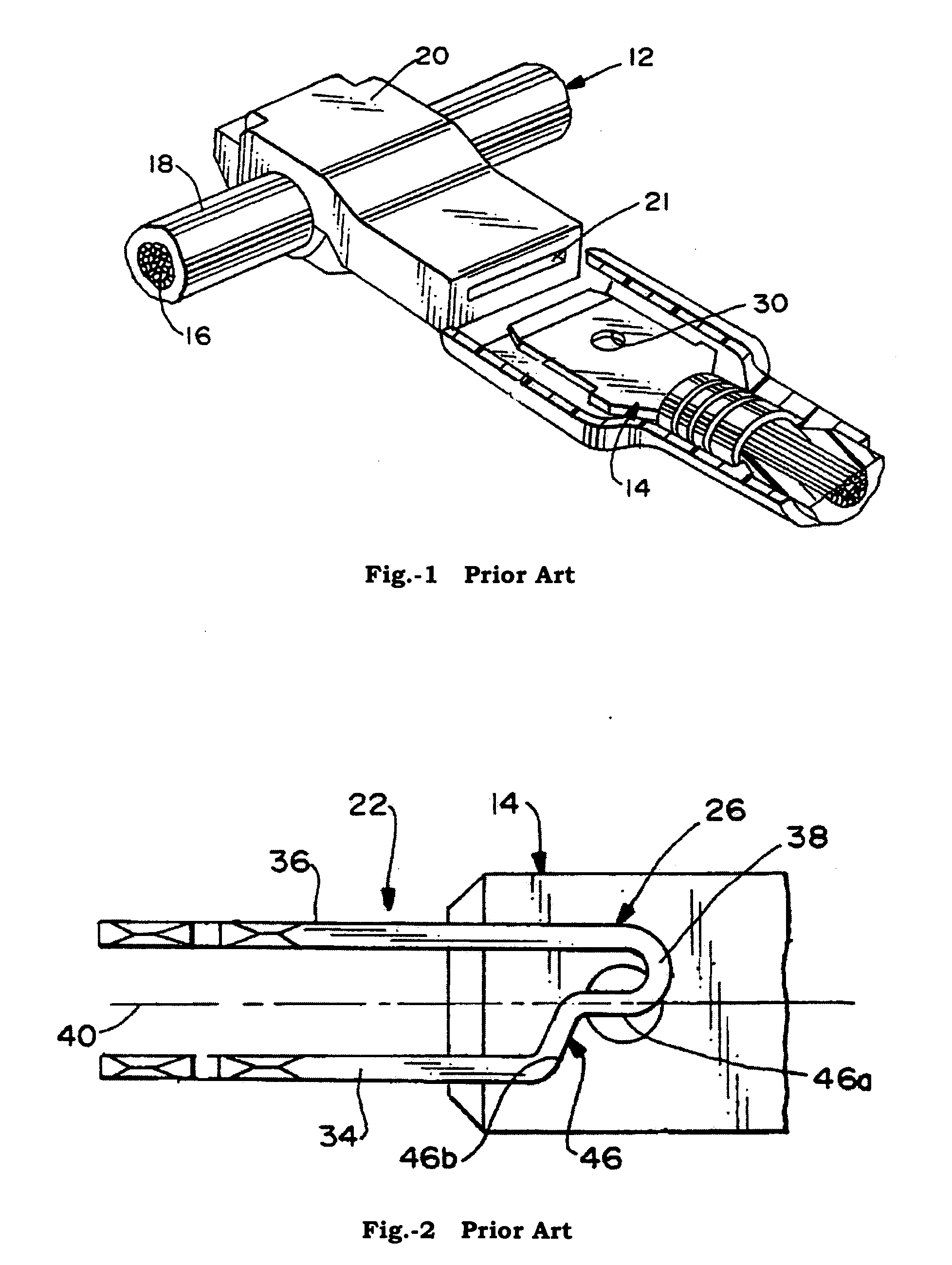
[0022] Because one type of stamped terminal for connecting an insulated wire to a blade contact which is mounted by an insulated housing has been disclosed in prior art, the following illustration doesn't make an integral description of it. The function of the drawings in the following contexts which aren't drawn in accordance with the real related dimension is to show the characteristic of the present invention.

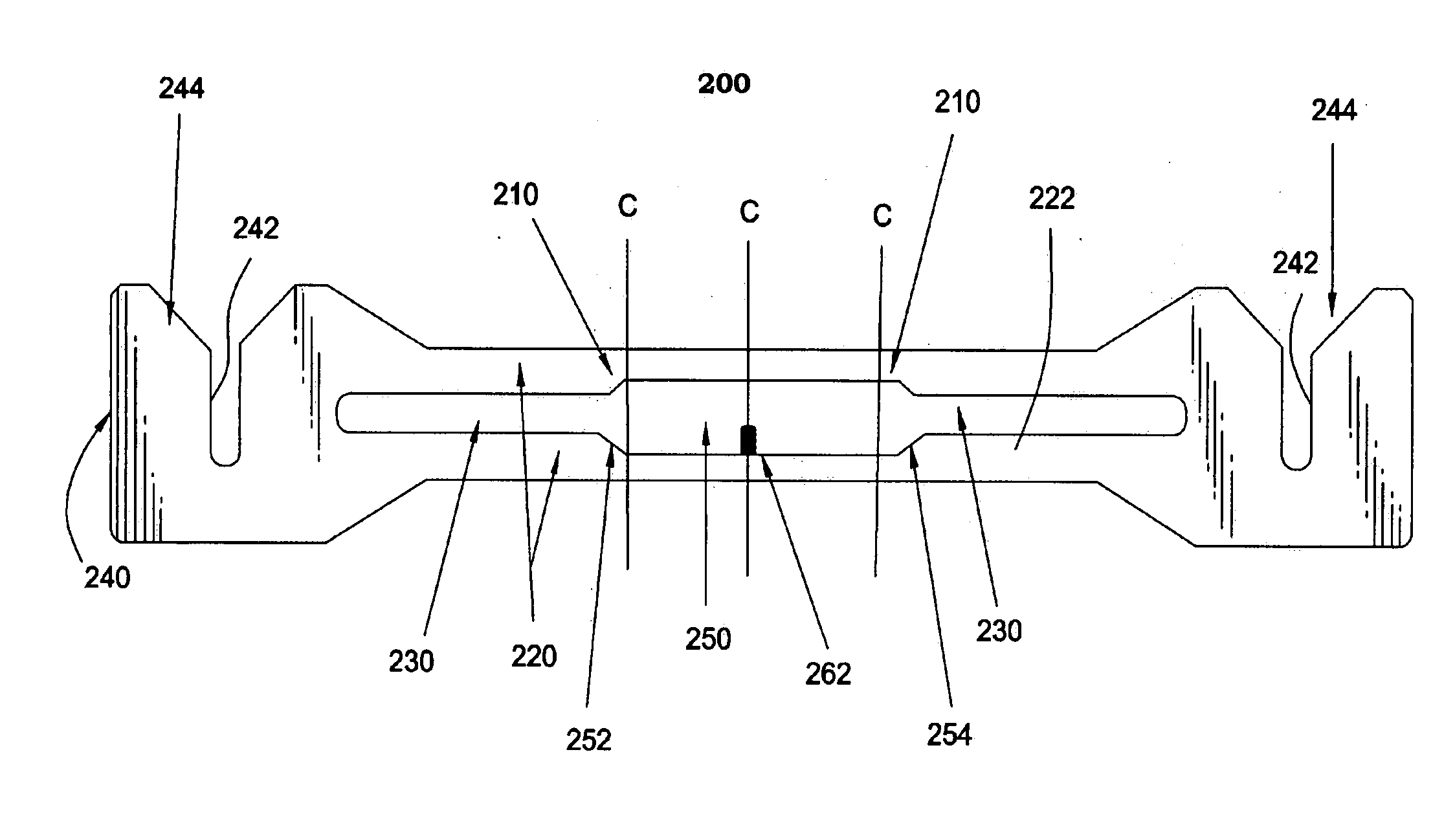
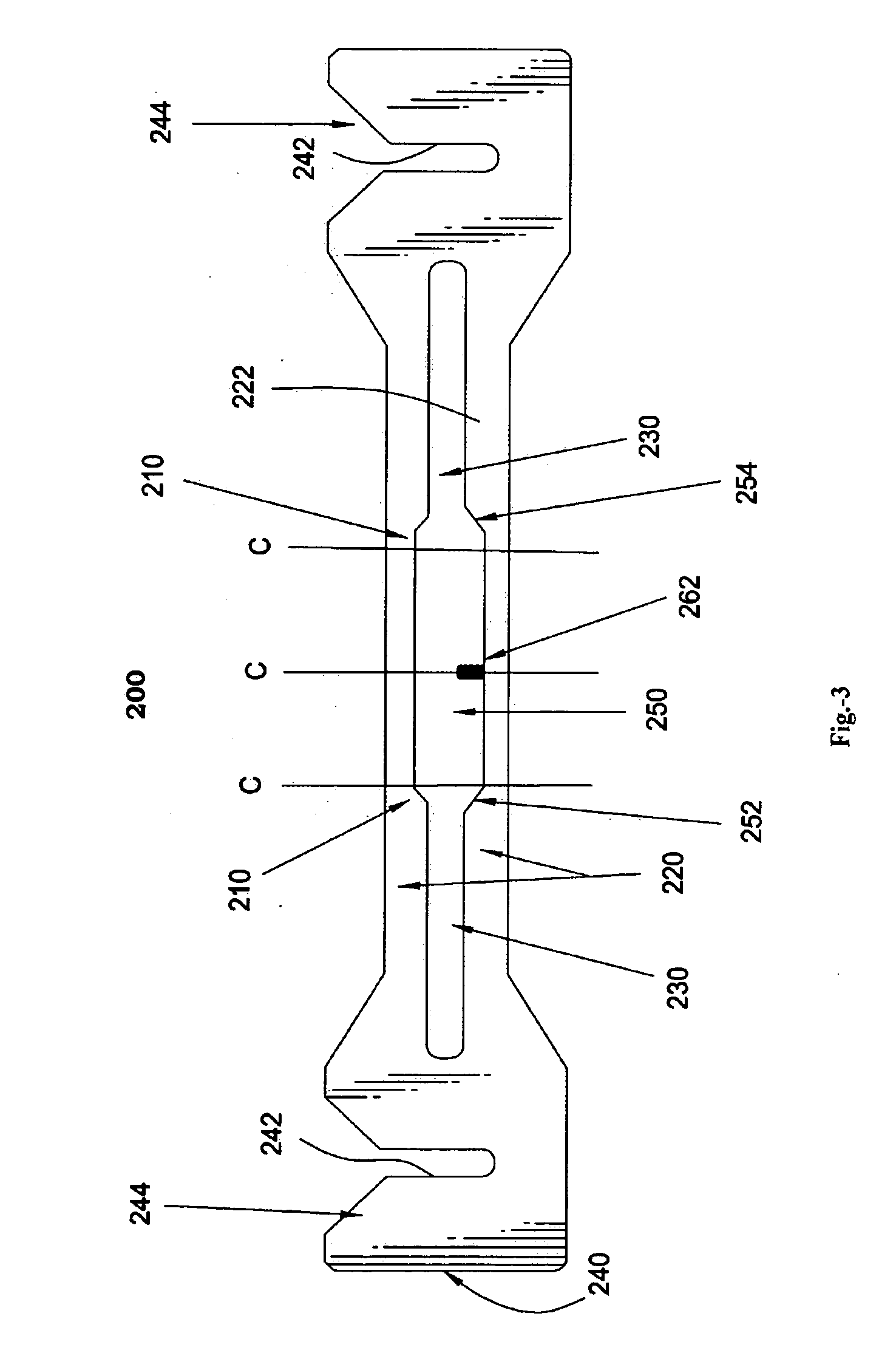
[0023] First to FIG. 3, is a configuration of stamped and formed metal sheet with a subsequently W-shaped blade-receiving terminal (200). The metal sheet showed in FIG. 3 includes a pair of leg portions (220,222) in which a transverse slot(230) is defined. The leg portions(220,222) are extended to have two free ends(240) on each which has a longitudinal slot(242). Besides, nearby the central area of the metal sheet has an enlarged transverse slot(250). The enlarged transverse slot(250) and the transverse slot (230)defined by the pair of leg portions(220,222) are connected b...


PUM


Abstract

An electrical-tap connector has a blade-receiving portion and a wire-receiving portion for connecting a wire and a blade contact. The electrical-tap connector includes an integrally insulated housing which mounts a generally W-shaped metal sheet therein. The generally W-shaped metal sheet includes a pair of apexes and a pit therebetween. The respective one ends of the apexes are joined by a parallel leg portions with free ends at the end of the leg portions. A transverse slot is defined in the transverse direction of the generally parallel leg portions. A longitudinal slot is defined in the longitudinal direction of the free ends and an oblique face lead-in mouth is defined at the entrance of the longitudinal slot.

Description

BACKGROUND OF THE INVENTION [0001] 1. Field of Invention [0002] The present invention generally relates to the art of electrical-tap connectors and, particularly to a stamped electrical-tap connector assembly having a wire-receiving portion at one end and a blade-receiving portion at the other end. [0003] 2. Description of Related Art [0004] In the modern digital era, for the system functioning well, the individual device or signal or electricity need to be connected together. Therefore, it needs many connectors to connect the above. [0005] Many electrical connectors or terminals have been designed for receiving or mating with a male tab or blade contact. Such electrical connectors or terminals often are used in tap connectors for making a T-connection to an insulated electrical wire. In such connectors, one end of the terminal includes an insulation displacement terminal(i.e. IDT), wire-receiving portion, and the opposite end of the terminal includes a mating or blade-receiving por...

Claims


Application Information

Patent Timeline
Patent Type & Authority Applications(United States)
IPC IPC(8): H01R4/24
CPCH01R4/2425H01R13/113H01R11/05
Inventor CHENG, I-TIEN
Owner KS TERMINALS INC
Why Eureka
Try Eureka