Closed electroosmosis drive method and electroosmosis drum

An electroosmotic-driven, closed-type technology, applied in the field of electrochemistry, can solve the problems of contamination by the transmission fluid, clogging of air bubbles, inconvenient use, etc., and achieve the effect of stable pH value, avoiding clogging of air bubbles, and prolonging service life.

Inactive Publication Date: 2004-10-13
UNIV OF SCI & TECH OF CHINA
View PDF3 Cites 5 Cited by
  • Summary
  • Abstract
  • Description
  • Claims
  • Application Information

AI Technical Summary

Problems solved by technology

[0003] The above-mentioned technologies mainly use unidirectional electrolytic current to drive liquid transmission. Generally, no diaphragm is used to isolate the electroosmosis liquid from the liquid to be transferred. They are all open electroosmotic devices, so the electrolysis products on the electrodes will contaminate the liquid to be transferred, and the electroosmotic current will leak. Into the transported liquid, easy to generate air bubbles and cause blockage, and the input and output pipes of the electroosmotic fluid make the device very complicated and inconvenient to use, which restricts the wider application of electroosmotic technology

Method used


Image

  • Closed electroosmosis drive method and electroosmosis drum
  • Closed electroosmosis drive method and electroosmosis drum
  • Closed electroosmosis drive method and electroosmosis drum

Examples


Embodiment 1

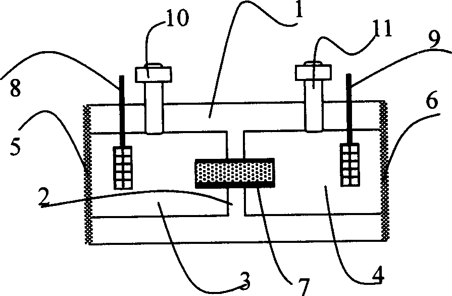
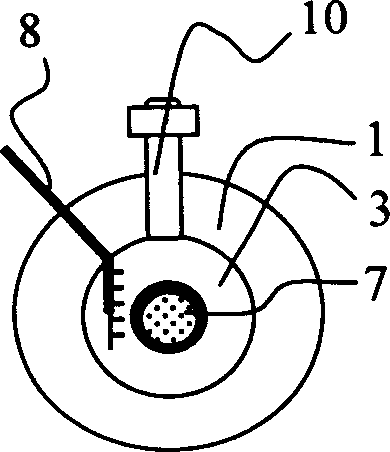
[0032] Embodiment 1: Diaphragm drum in the electroosmosis drum of the present invention

[0033] In the middle part of a drum body 1 made of plexiglass, a plexiglass drum partition 2 divides the tympanic cavity laterally into a front tympanic cavity 3 and a rear tympanic cavity 4, and a silicon rubber film is respectively covered at the openings of the tympanic cavity 3 and 4. Tympanic membranes 5 and 6, a glass sand core electroosmotic column 7 runs through the tympanic septum 2 and is sealed with epoxy resin, and platinum black electrodes 8 and 9 are respectively installed in the tympanic cavity 3 and 4, and their electrode wires are led out to the closed Outside the tympanic cavity; the corresponding drum bodies of the tympanic cavity 3 and 4 are respectively equipped with stainless steel valves 10 and 11, through which the tympanic cavity 3 and 4 are respectively injected and filled with a concentration of 0-1.0mmol / l diethanolamine or After the electroosmotic solution of ...

Embodiment 2

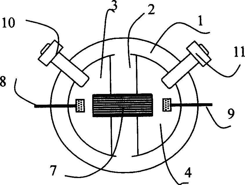
[0036] Example 2: Mediastinal drum in the electroosmotic drum of the present invention

[0037] In a drum body 1 made of polytetrafluoroethylene, there is a longitudinal septum 2 that separates the drum cavity into a left sub-tympanic cavity 3 and a right sub-tympanic cavity 4, and the two ends of the drum cavity 3 and 4 are respectively covered with Elastic membrane tympanic membranes 5 and 6 of electrically insulating material, a quartz capillary electroosmosis column 7 runs through the tympanic septum 2 and is sealed with epoxy resin, platinum mesh electrodes 8 and 9 are respectively set in the tympanic cavity 3 and 4, and the left and right drums The body is provided with valves 10 and 11 respectively, through the valves 10 and 11, the tympanic cavity 3 and 4 are filled with ammonia water with a concentration of 0-1.0mmol / l as the electroosmotic fluid, and the valves 10 and 11 are closed, that is, as attached image 3 (top perspective view) and attached Figure 4 (Side pe...

Embodiment 3

[0039] Example 3: Diaphragmatic electroosmotic drums connected in series

[0040] More than two transverse electroosmotic drums 12 are arranged head to tail in the same direction and fixed on the base 13, the tympanic membrane of the former electroosmotic drum is bonded with the tympanic membrane of the latter electroosmotic drum through the connecting block 14, as attached Figure 5 As shown, it is a series diaphragm drum.

[0041] When in use, apply an alternating voltage or current with a certain period and phase on the two electrodes of each electroosmotic drum, and keep the electrolytic electric quantity integrals in the two directions of each cycle equal. Vibration output with superimposed waveform and intensity is obtained on the drums at both ends. In a typical situation, if an alternating voltage or current with the same amplitude and phase is applied to the two electrodes of each electroosmotic drum, the output with the same waveform and energy addition can be obtai...


PUM


Abstract

The present invention discloses a closed electroendosmotic driving method and electro-endosmotic drum. It has two drum cavities in which the electroendosmosis solution is held respectively, said two drum cavities are communicated by means of electroendosmotic column, said drum cavity is covered with drum membrane, in the interiour of drum cavity the electrode is set respectively, and the electroendosmosis solution and electrode are formed into electroendosmotic pump, on two electrodes the current whose polarity is alternatively changed on be passed through, and the integrals of electrolytic quantities of two directions of every cycle are identical, so that the reciprocating flow of electroendosmosis solution in the electroendosmotic column can be formed so as to result in drum membrane vibration to output mechanical vibration as electroendosmotic driving source to form a closed electric driving device. It can be conveniently series-connected, paralellly-connected and combined to form complex driving system.

Description

technical field [0001] The invention belongs to the technical field of electrochemistry, and in particular relates to an electroosmosis driving method and a device thereof. Background technique [0002] Electroosmosis is widely used in micro-flow control. For example, a micro-flow device proposed by US patent application US005965001A uses electro-osmotic flow to drive the fluid in the pipeline, making the transmission process precise and controllable, and easy to automate; US patent application US006012902A will This technology has developed into a micropump that can be microfabricated on a tiny chip; Chinese patent CN2286429Y uses a sand core column electroosmotic pump for liquid transmission. [0003] The above-mentioned technologies mainly use unidirectional electrolytic current to drive liquid transmission. Generally, no diaphragm is used to isolate the electroosmosis liquid from the liquid to be transferred. They are all open electroosmotic devices, so the electrolysis ...

Claims


Application Information

Patent Timeline
Patent Type & Authority Applications(China)
IPC IPC(8): B01D61/42B01L3/00G01N27/447
Inventor 林祥钦蒋晓华何友昭
Owner UNIV OF SCI & TECH OF CHINA
Why Eureka
Try Eureka