
Method for manufacturing high-reliability optical filter

A manufacturing method and filter technology, applied in ion implantation plating, metal material coating process, coating and other directions, can solve problems such as poor control of internal stress, difficult temperature control, inability to meet, etc., to improve product mechanics Features, not easy to release, the effect of improving yield

Pending Publication Date: 2021-06-11
深圳正和捷思科技有限公司
View PDF5 Cites 0 Cited by
  • Summary
  • Abstract
  • Description
  • Claims
  • Application Information

AI Technical Summary

Problems solved by technology

The traditional process of preparing optical filters mainly adopts normal temperature evaporation to form a film, which requires a low degree of vacuum and a low material deposition rate; for a filter with a thicker film layer, it will cause greater internal stress and poor adhesion. Phenomenon
The defects of the above-mentioned process are: the internal stress of the product is large, and the poor adhesion and the release of the internal stress of the film layer during the cutting process will cause the film layer to fall off and the glass to chip and crack.
The internal stress is caused by the vacuum degree of the cavity during the coating process and the difference in thermal expansion coefficient between the film layer and the substrate. The evaporation of the film material will generate heat. When the film material is switched and evaporated, the temperature of the cavity and the glass substrate It is difficult to control, which will cause large fluctuations in the temperature of the cavity, so the internal stress is not easy to control
In the process of cutting the filter into small particles, the film will be stripped, chipped and cracked, and the reliability is poor, resulting in a 23% reduction in product yield, which cannot meet customer requirements

Method used


Image

  • Method for manufacturing high-reliability optical filter
  • Method for manufacturing high-reliability optical filter

Examples


Embodiment

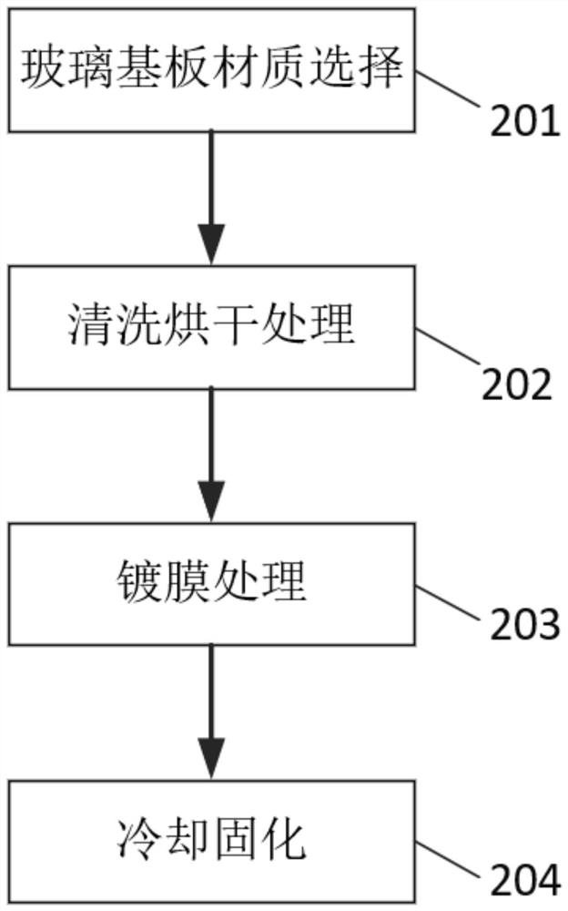
[0031] Such as Figure 1-Figure 2 As shown, this embodiment provides a method for manufacturing a high-reliability optical filter, and the specific technical solution is as follows:

[0032] A method for manufacturing a high-reliability optical filter, comprising the following steps:

[0033] Glass substrate 1 material selection: choose quartz glass with a hardness up to Mohs grade 7, high temperature resistance, low expansion coefficient, good chemical stability and a size of 40X40X0.88mm.

[0034] Specifically, quartz glass has a hardness of up to seven on the Mohs scale and has high temperature resistance. Its regular use temperature is 1100°C to 1200°C, and its short-term use temperature can reach 1400°C. It has a low expansion coefficient, which is 1 / 10 to 1% of ordinary BK7 glass. / 20. And thermal shock resistance, chemical stability and electrical insulation performance are good, and can pass through ultraviolet and infrared rays;

[0035] Cleaning and drying treatme...


PUM


Abstract

The invention provides a method for manufacturing a high-reliability optical filter. The method comprises the steps of: selecting quartz glass with high hardness, high temperature resistance, low expansion coefficient and good chemical stability; cleaning, drying and storing a glass substrate; before coating, carrying out high vacuum extraction on a coating jig to stabilize the vacuum degree of the coating jig between 1.0 E and 3 Pa, simultaneously heating a cavity in the coating jig and the cleaned and dried glass substrate to 220 DEG C at a constant temperature, loading the glass substrate heated at the constant temperature on an umbrella stand of the coating jig, and carrying out evaporation coating on the glass substrate by using a Ti3O5 material with a high refractive index and a SiO2 material with a low refractive index; and naturally cooling the coated glass substrate, and filling high-purity nitrogen into the cavity of the coating jig to cure the cooled glass substrate. Compared with the prior art, the method has the advantages that the mechanical property of a product can be improved, the optical filter with high reliability can be manufactured, and the problems that in the prior art, the product yield is not high, and the optical filter is prone to demolding, edge breakage and corner cracking can be solved.

Description

technical field [0001] The invention relates to the technical field of optical thin films, in particular to a method for manufacturing a high-reliability optical filter. Background technique [0002] Filters are optical devices used to select the desired wavelength band of radiation. One commonality of filters is that no filter will make the image of a celestial object brighter, because all filters will absorb certain wavelengths, making the object darker. [0003] Driven by the rapid development of the optical communication industry, the demand for optical filters has also increased significantly. In addition to certain optical properties, the optical film should also have mechanical properties suitable for its application, such as sufficient mechanical strength, good adhesion to the glass substrate, appropriate internal stress state, etc. The microscopic properties of the film Structure plays an important role in influencing its mechanical properties. The traditional pr...

Claims


Application Information

Patent Timeline
IPC IPC(8): C23C14/02C23C14/08C23C14/10C23C14/24C23C14/58
CPCC23C14/24C23C14/10C23C14/083C23C14/584C23C14/021
Inventor 陈国彦刁兆俊蔡喜斌华秀菊
Owner 深圳正和捷思科技有限公司
Learn More