Trajectory-based deep-brain stereotactic transcranial magnetic stimulation

a transcranial magnetic stimulation and trajectory-based technology, applied in the field of system for stereotactic transcranial magnetic stimulation of the brain, can solve the problems of preventing the effect of simply increasing the output of the electromagnet, limiting the rtms technique to the stimulation of only superficial structures, and limiting the tms and rtms instruments

Active Publication Date: 2007-11-08
THE BOARD OF TRUSTEES OF THE LELAND STANFORD JUNIOR UNIV +1
View PDF57 Cites 108 Cited by
  • Summary
  • Abstract
  • Description
  • Claims
  • Application Information

AI Technical Summary

Problems solved by technology

TMS and rTMS instrumentation are currently limited by their inability to focus their magnetic fields at depth.
While stimulation has shown promise in the treatment of depression, the limitation of the rTMS technique to the stimulation of only superficial structures has been a significant restriction.
Unfortunately, simply increasing the output of the electromagnet is prevented from achieving the desired effect because of the proportional increase at the superficial location, where the field is much stronger to begin with.
The resultant magnetic field could easily overwhelm the superficial structures and cause pain, unintended activation of non-targeted structures, possibly seizures and neural excitotoxicity.
Because TMS apparatuses are physically large and bulky, and because their use at effective power levels is generally not comfortable, applying continuous stimulation over a period of hours, days or beyond is not practical.
Unfortunately, the smaller the coil, the less field strength it is able to generate at any given level of electrical input.
Increasing the current vastly increases the cooling needs of the magnets.
Because of the rapid rate of magnetic field strength fall off with distance from the coil, and the difficulty in providing efficient cooling mean, highly focal coils tend to have little ability to penetrate to depth.
This factor limits the ability for the magnetic fields of small coils to penetrate to depth.
However this improved depth penetration is achieved with an overall decline in locality when compared with conventional coils.
Unfortunately, DBS necessarily involves an invasive neurosurgical procedure, which is expensive, and fraught with medical risks including intracranial bleeding and infection.
However, this work did not produce or teach a magnetic coil configuration that would enable the intensity at depths to exceed that on the surface, and no further efforts at improving the process were documented.

Method used


Image

  • Trajectory-based deep-brain stereotactic transcranial magnetic stimulation
  • Trajectory-based deep-brain stereotactic transcranial magnetic stimulation
  • Trajectory-based deep-brain stereotactic transcranial magnetic stimulation

Examples


Embodiment Construction

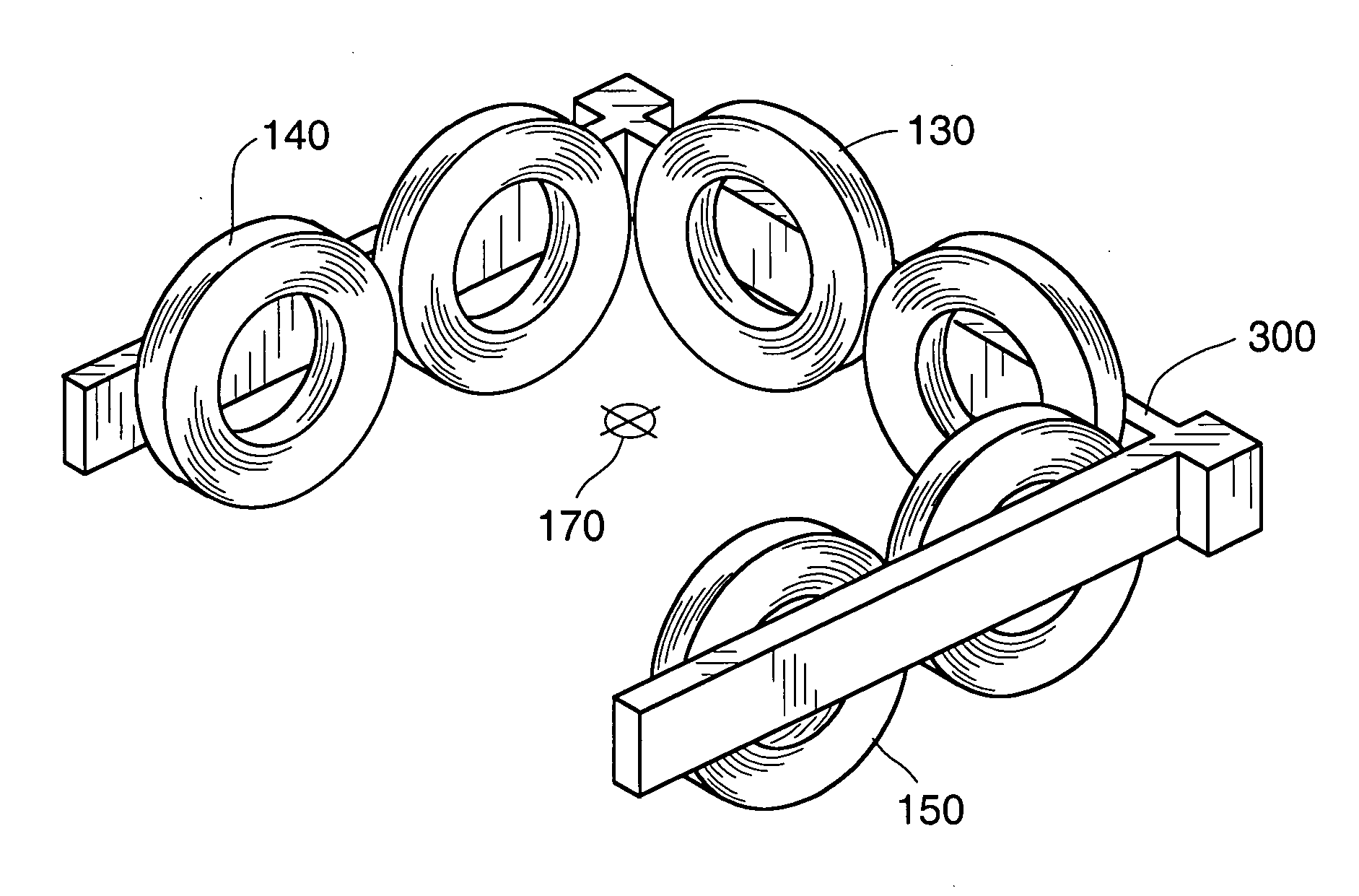
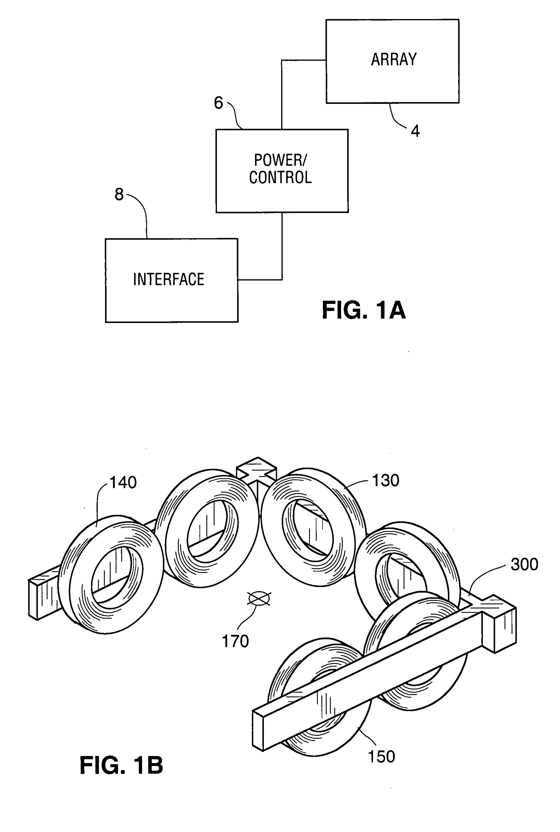
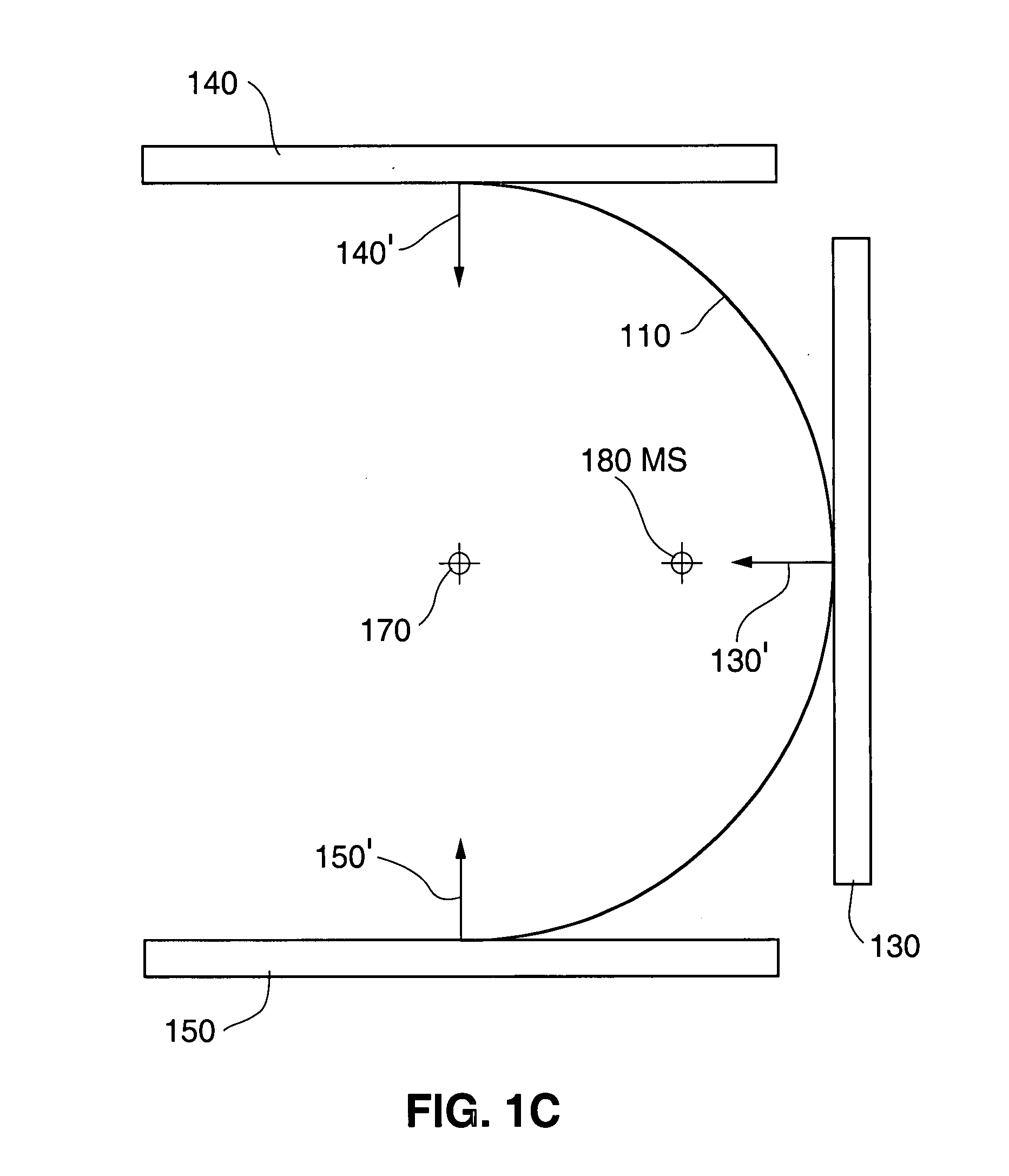
[0051] The present application describes a system and method for stereotactic transcranial magnetic stimulation or modulation (“sTMS”). The disclosed system and method uses an array of coils arranged in a predetermined configuration and pulsed substantially simultaneously so that at select spatial vectors, the magnetic field strength at a deep target exceeds that on the surface, close to the coils.

[0052] The disclosed method derives its effect, in part, by recognizing that in addition to considering total magnetic field strength at a given location, consideration of the strength and direction of individual X, Y, and Z magnetic vectors from an array of coils allows an arrangement of the coils to be selected such that the magnetic fields of the magnets will combine in a manner that intensifies some areas of the overall magnetic field and weakens others. In the appropriate configuration, the magnetic field along a given axis (say, for the purposes of one example, the Z-Axis defined as...


PUM


Abstract

The present invention provides for Stereotactic Transcranial Magnetic Stimulation (sTMS) at predetermined locations with the brain or spinal cord and incorporates an array of electromagnets arranged in a specified configuration where selected coils in the array are pulsed simultaneously. Activation of foci demonstrated by functional MRI or other imaging techniques can be used to locate the neural region affected. Imaging techniques can also be utilized to determine the location of the designated targets.

Description

FIELD OF INVENTION [0001] This invention relates to systems for Stereotactic Transcranial Magnetic Stimulation of the brain to modulate neural activity at arbitrary deep and superficial brain locations. BACKGROUND OF THE INVENTION [0002] Transcranial Magnetic Stimulation (TMS) and Repetitive Transcranial Magnetic Stimulation (rTMS, a variant of TMS in which electromagnetic fields are produced in trains of multiple short pulses) have shown the ability to trigger neuronal firing in selected superficial brain regions. In at least one psychiatric condition (major depression), this effect of TMS and of rTMS appears to constitute an effective therapy. TMS and rTMS instrumentation are currently limited by their inability to focus their magnetic fields at depth. This is chiefly because a magnetic field always diminishes as a function its distance from the source. [0003] Several techniques have been used to deliver stimulation to deep regions of the brain, as will be described. In the use of...

Claims


Application Information

Patent Timeline
Patent Type & Authority Applications(United States)
IPC IPC(8): A61N2/00A61N1/00A61B17/52
CPCA61N2/004A61N2/02A61N2/008A61N2/006
Inventor MISHELEVICH, DAVIDSCHNEIDER, M.
Owner THE BOARD OF TRUSTEES OF THE LELAND STANFORD JUNIOR UNIV
Why Eureka
Try Eureka