
Dynamic vehicle suspension system testing and simulation

a suspension system and dynamic technology, applied in the field of vehicle suspension system testing and evaluation, can solve the problems of time-consuming and expensive track tests, inability to instantly compensate for body roll, and drawbacks of both track tests and conventional simulations

Inactive Publication Date: 2007-11-08
MTS SYSTEMS CORPORATION
View PDF7 Cites 96 Cited by
  • Summary
  • Abstract
  • Description
  • Claims
  • Application Information

AI Technical Summary

Benefits of technology

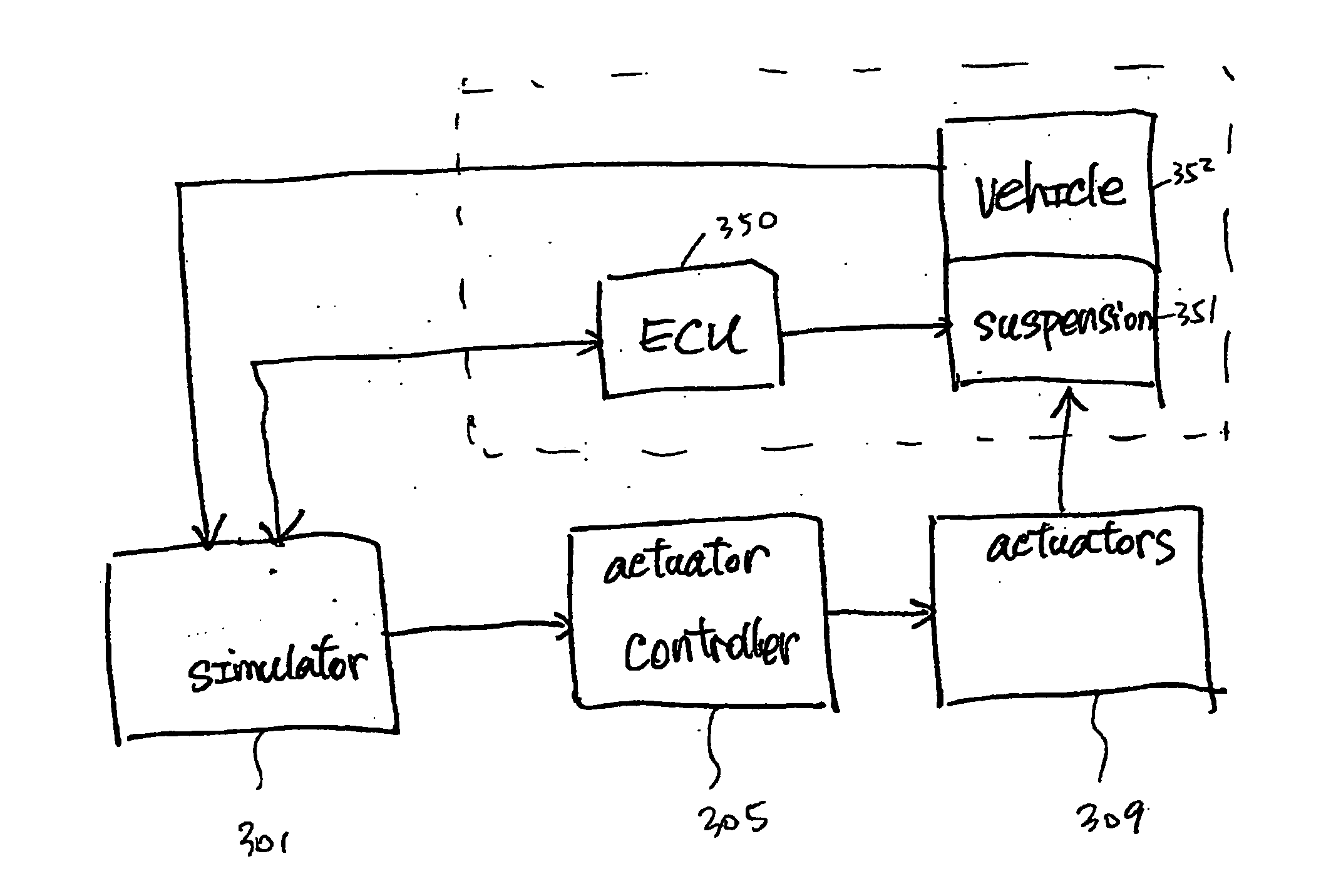
[0010] This disclosure describes embodiments of vehicle simulations that address some or all of the above-described needs. An exemplary tester for testing a vehicle suspension subsystem includes at least one test rig actuator configured to apply a test condition to the subsystem, and at least one sensor configured to collect signals related to the subsystem. A data processing system, such as a computer, is provided and includes a data storage device configured to store data related to a simulation model related to the vehicle and machine-executable instructions. The instructions,

Problems solved by technology

It will not instantly compensate for body roll due to cornering however.
However, both track tests and conventional simulations have drawbacks.
Track tests usually are time consuming and expensive.
In some cases, track tests are impractical or even impossible because a finalized design of a new vehicle may be unavailable to determine the interactions between one or more subsystems of the vehicle and the vehicle itself.
Conventional HIL simulations, though less expensive than track tests, only evaluate electronic signals between the circuit under test and the vehicle model, but do not test the combination of electronic, software and mechanical components collectively in the presence of real forces and motion.

Method used


Image

  • Dynamic vehicle suspension system testing and simulation
  • Dynamic vehicle suspension system testing and simulation
  • Dynamic vehicle suspension system testing and simulation

Examples


Embodiment Construction

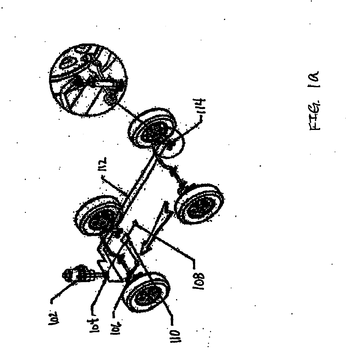
[0026] For illustration purposes, the following descriptions describe various illustrative embodiments of testers for testing a vehicle, such as an automobile, airplane, etc.; and / or one or more subsystems thereof, such as an actively controlled suspension system, active rolling control system, etc. It will be apparent, however, to one skilled in the art that concepts of the disclosure may be practiced or implemented without these specific details. In other instances, well-known structures and devices are shown in block diagram form in order to avoid unnecessarily obscuring the present disclosure.

[0027] An automobile includes various subsystems for performing different functions such as power train, driver interface, climate and entertainment, network and interface, lighting, safety, engine, braking, steering, chassis, etc. Each subsystem further includes components, parts and other subsystems. For instance, a power train subsystem includes a transmission controller, a continuously...


PUM


Abstract

A dynamic vehicle tester providing integrated testing and simulation for determining characteristics of a unit under test. Changes occurred on the unit under test are dynamically obtained, considered and incorporated in generating test conditions to be applied to the unit under test. In particular, testing of a vehicle suspension system may be accomplished.

Description

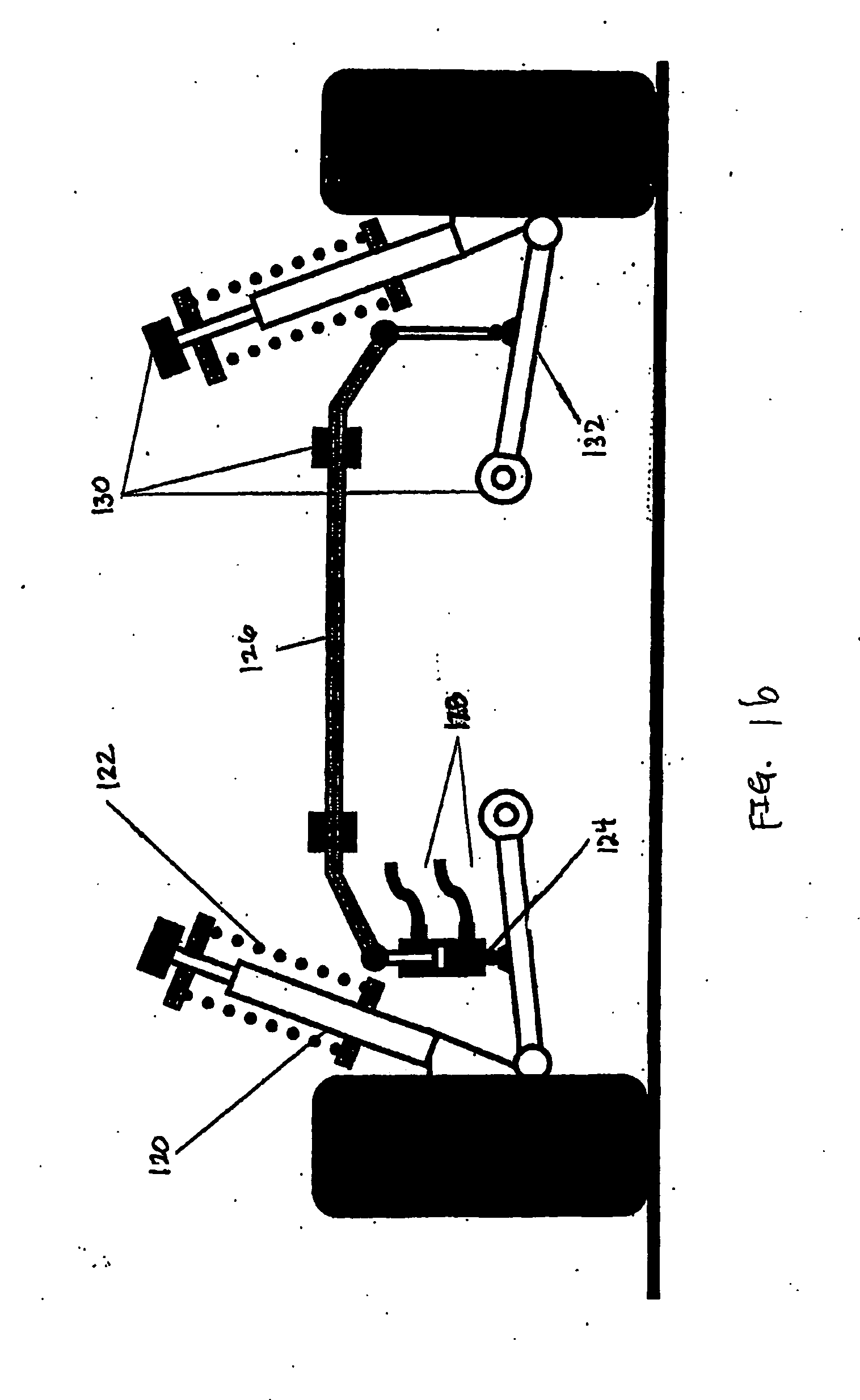
FIELDS OF DISCLOSURE [0001] This application generally relates to vehicle testing and evaluations, and more specifically, to an integrated and physical testing approach for testing a vehicle's suspension system. BACKGROUND [0002] The term “suspension” usually refers to the system of springs, shock absorbers and linkages that connects a vehicle to its wheels. Suspension systems serve a dual purpose—contributing to the car's handling and braking for good active safety and driving pleasure, and keeping vehicle occupants comfortable and reasonably well isolated from road noise, bumps, and vibrations. These goals are generally at odds, so the tuning of suspensions involves finding the right compromise. The suspension also protects the vehicle itself and any cargo or luggage from damage and wear. Design of front and rear suspension of a car is typically different. [0003] Traditional springs and dampers are referred to as passive suspensions. If the suspension is externally controlled then...

Claims


Application Information

Patent Timeline
IPC IPC(8): G06F19/00
CPCG01M17/04
Inventor LANGER, WILLIAM
Owner MTS SYSTEMS CORPORATION
Learn More