Drier

a drying machine and drying chamber technology, applied in the field of drying machines, can solve problems such as difficulty in in situ assembly of conveying devices, and achieve the effect of easy assembly

Active Publication Date: 2007-11-15
DUERR SYST AG
View PDF39 Cites 13 Cited by
  • Summary
  • Abstract
  • Description
  • Claims
  • Application Information

AI Technical Summary

Benefits of technology

[0006] The underlying object of the present invention is to provide a drier of the initially described type, which is easy to assemble.

Problems solved by technology

In this case, the accessibility of the drier tunnel from two sides only and the confined spatial conditions in the drier tunnel make it difficult to assemble the conveying device in situ.

Method used


Image

  • Drier
  • Drier
  • Drier

Examples


Embodiment Construction

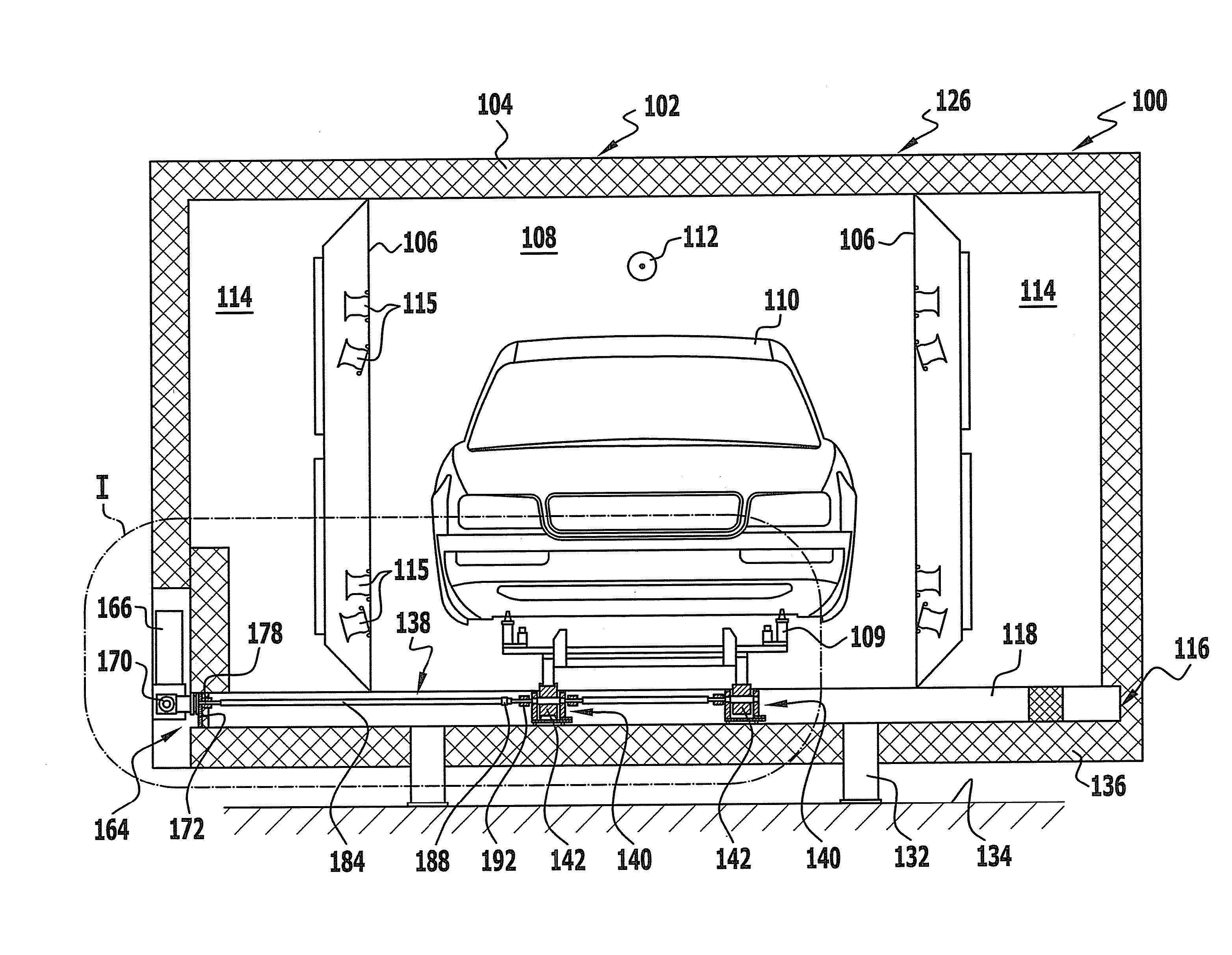
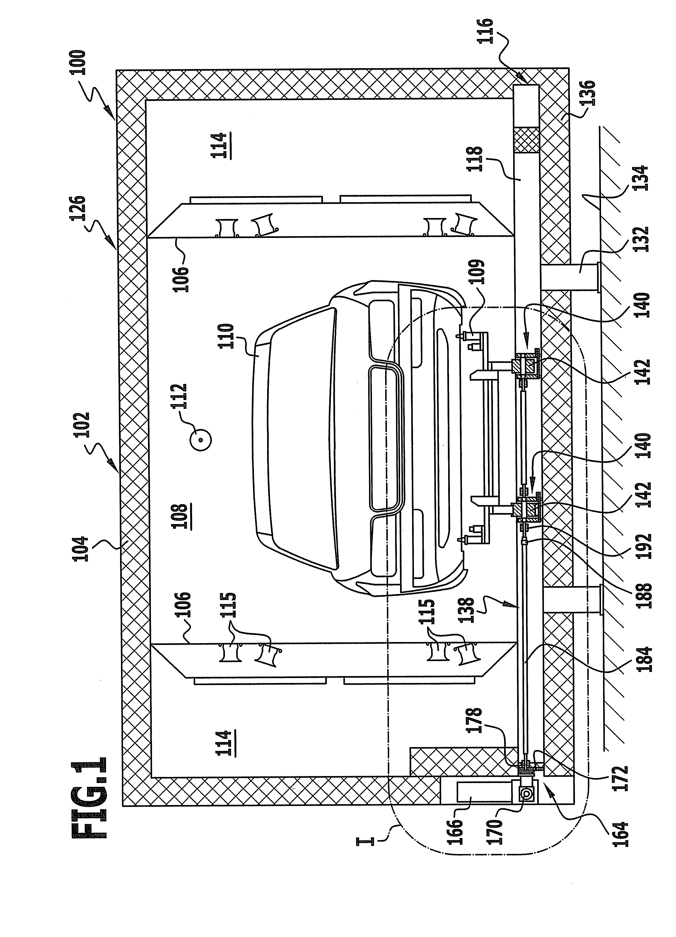
[0090] A drier represented in FIGS. 1 to 6 and denoted as a whole by 100 comprises a substantially cuboidal drier housing 102, which is provided with heat insulation 104.

[0091] The interior of the drier housing 102 is subdivided by means of vertical partitions 106 into a drier tunnel 108, through which vehicle bodies 110 disposed on in each case one skid frame 109 serving as a workpiece carrier are conveyed along a conveying direction 112 extending parallel to the longitudinal direction of the drier 100, and into two hot-air supply chambers 114 disposed on either side of the drier tunnel 108. The partitions 106 are provided with hot-air supply nozzles 115, through which hot air from the hot-air supply chambers 114 passes into the drier tunnel 108 to the vehicle bodies 110.

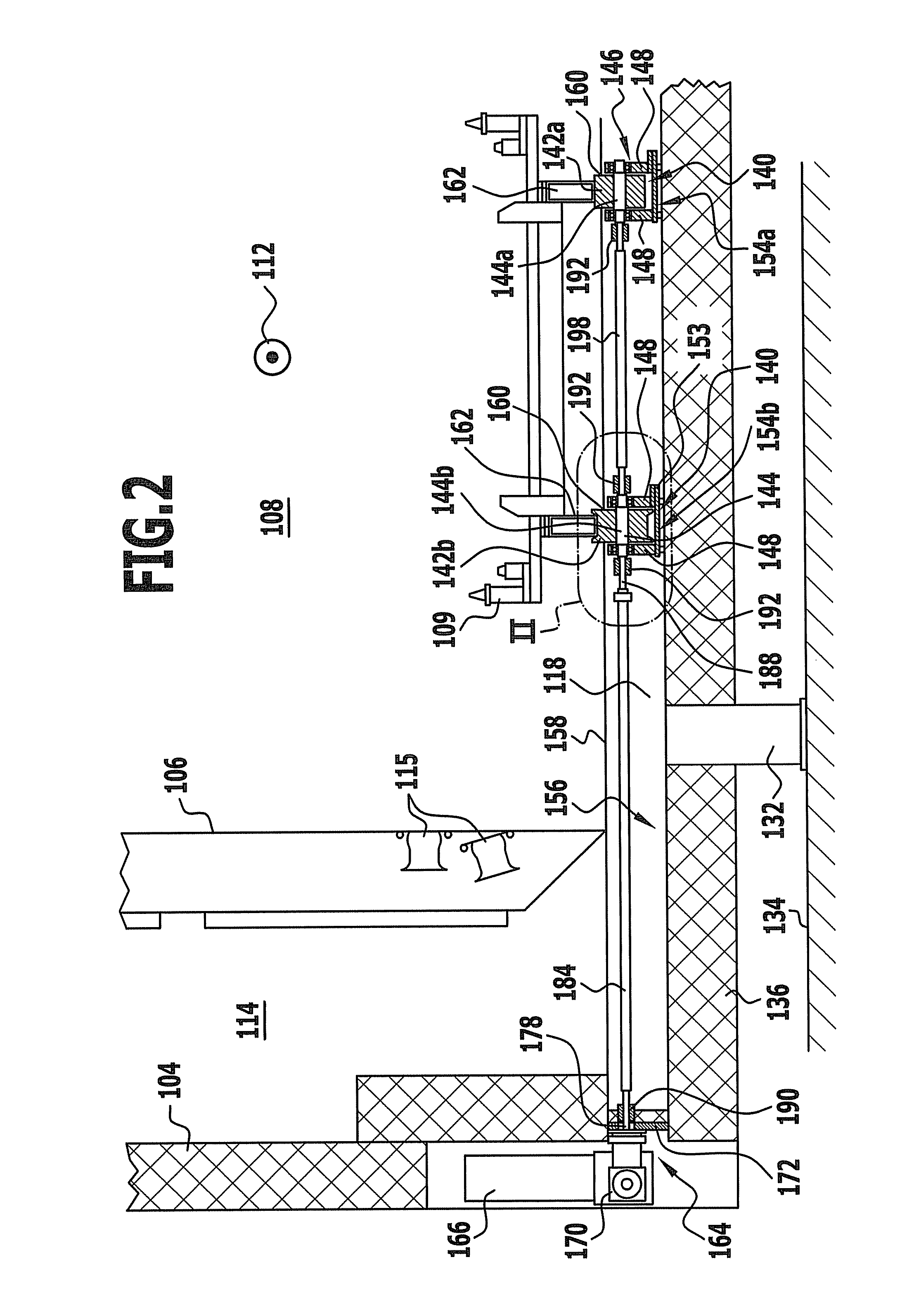
[0092] The drier floor denoted as a whole by 116 comprises, as load-bearing elements, floor elements 118, which take the form of hat-shaped profiles that extend horizontally and substantially at right angles to t...


PUM


Abstract

In order to provide an easy-to-assemble drier (100) for drying surface-treated workpieces, in particular vehicle bodies (110), which are each disposed on a respective workpiece carrier (109), comprising a drier housing (102) having a drier tunnel (108), through which the workpieces are moved along a conveying direction (112) and which is delimited in a downward direction by a drier floor (116) comprising a plurality of floor elements (118), and a conveying device (138) that conveys the workpieces through the drier tunnel (108), it is proposed that the conveying device (138) comprises a plurality of carrying roller units (140), which are disposed successively in the conveying direction (112) and each comprise at least one carrying roller (142), on which the workpiece carriers (109) rest as they are conveyed through the drier tunnel (108), wherein the carrying roller units (140) are each mountable separately on a respective floor element (118) of the drier floor (116).

Description

RELATED APPLICATION [0001] This application is a continuation application of PCT / EP2005 / 012000 filed Nov. 9, 2005, the entire specification of which is incorporated herein by reference.FIELD OF DISCLOSURE [0002] The present invention relates to a drier for drying surface-treated workpieces, in particular vehicles bodies, which are each disposed on a respective workpiece carrier, wherein the drier comprises a drier housing having a drier tunnel, through which the workpieces are moved along a conveying device and which is delimited in a downward direction by a drier floor comprising a plurality of floor elements, and a conveying device that conveys the workpieces through the drier tunnel. BACKGROUND [0003] Such driers are known from the prior art. [0004] In the known driers, the conveying device, that conveys the workpieces through the drier tunnel, is designed for example as a carrying-chain conveyor, in which a vehicle body disposed on a skid frame is placed by means of a rapid-remo...

Claims


Application Information

Patent Timeline
Patent Type & Authority Applications(United States)
IPC IPC(8): F26B25/06F26B25/00B65G13/00B65G13/02
CPCB60S3/002B65G13/02F26B2210/12B65G2201/0294F26B15/14B65G13/11B65G13/00
Inventor ORTLIEB, KONRADZURICH, HELMUTWESCHKE, JURGENNAPFEL, PETERFOTTINGER, MANFREDSTRAUSS, RUDOLF
Owner DUERR SYST AG
Why Eureka
Try Eureka