

Passenger rail car
a passenger rail and car technology, applied in the field of passenger rail cars, can solve the problems of incompatibility with single-level rail cars and operators at risk of serious injuries
- Summary
- Abstract
- Description
- Claims
- Application Information
AI Technical Summary
Benefits of technology
Problems solved by technology
Method used
Image

Examples
first embodiment
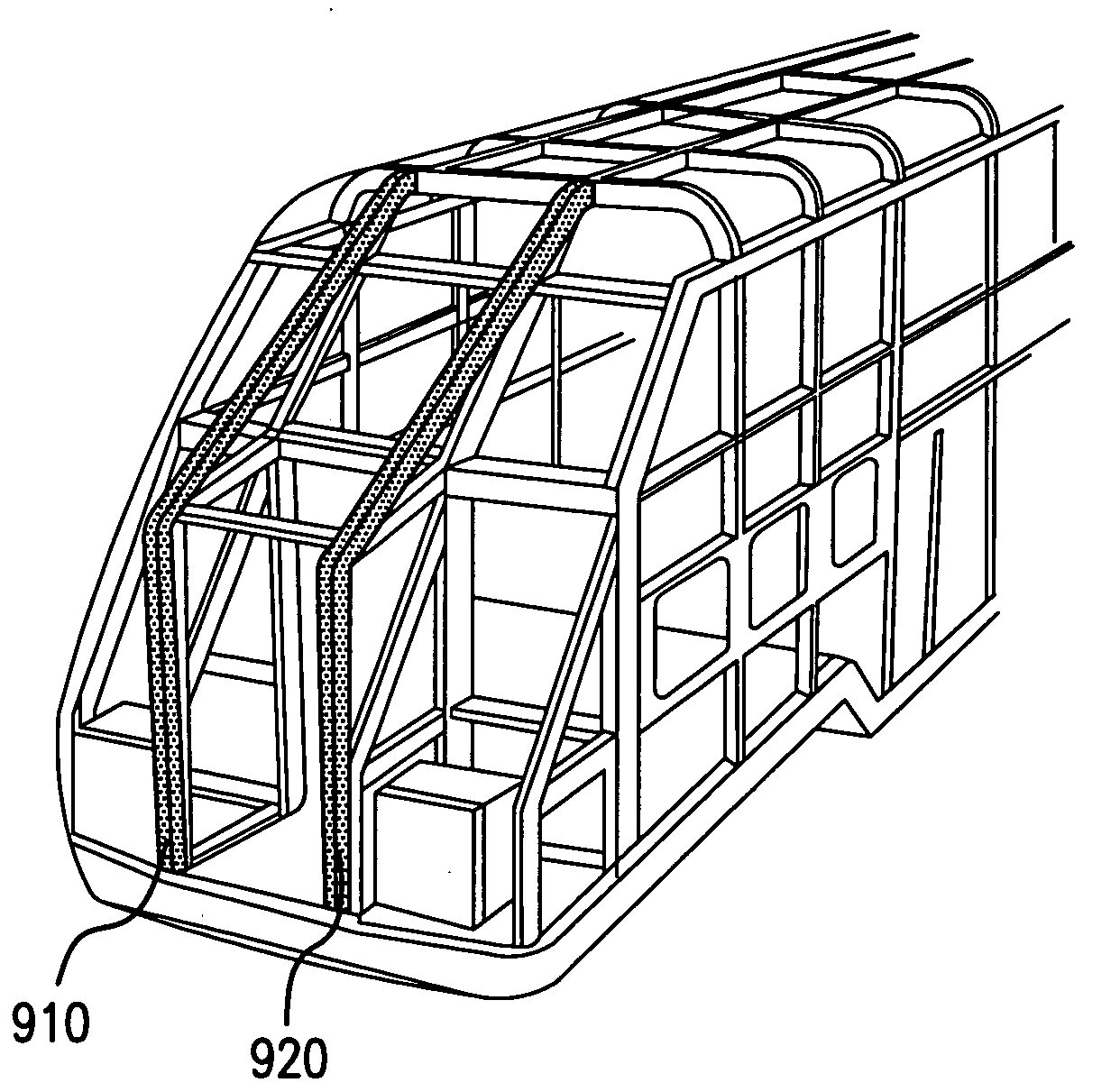
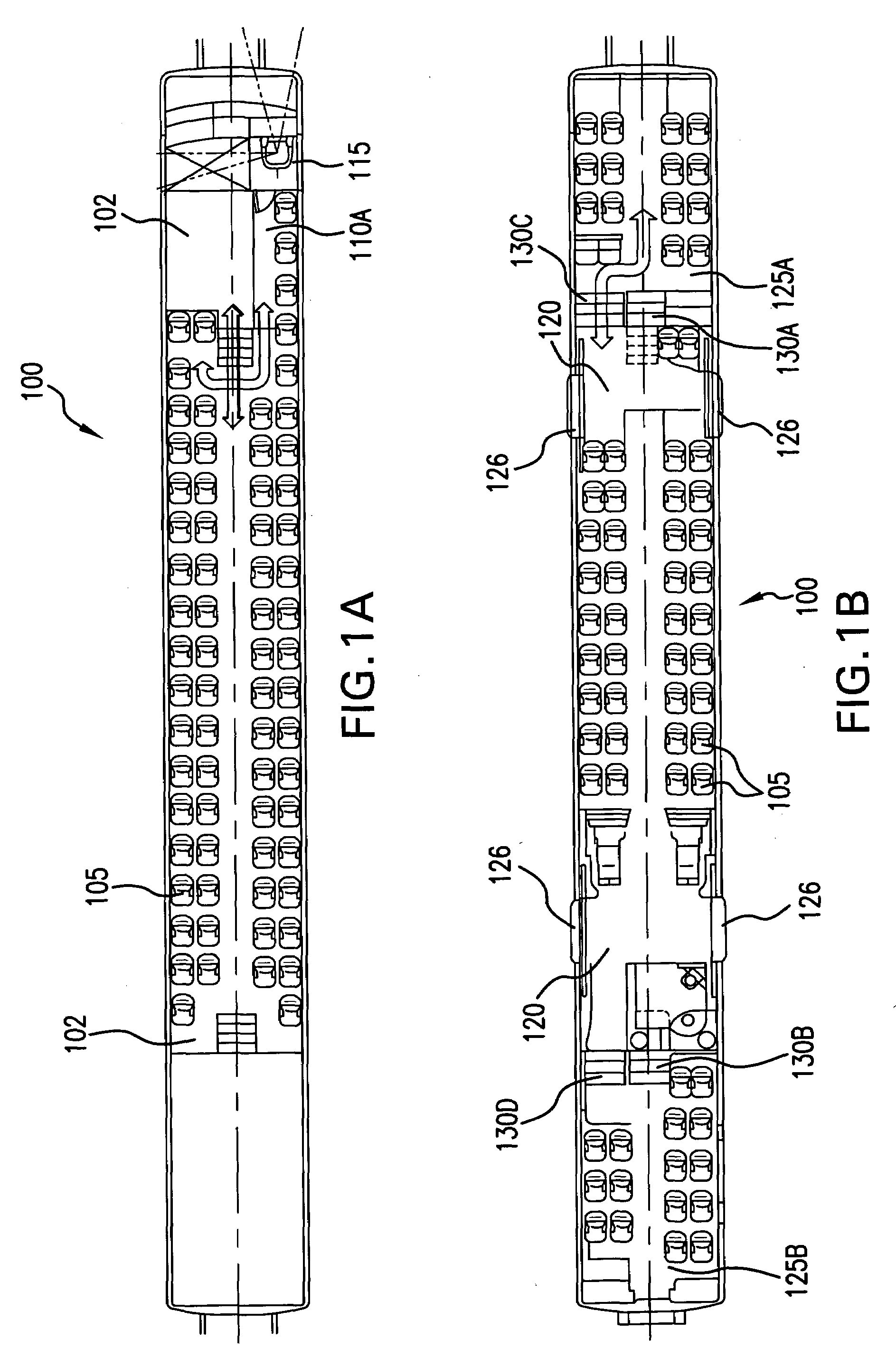
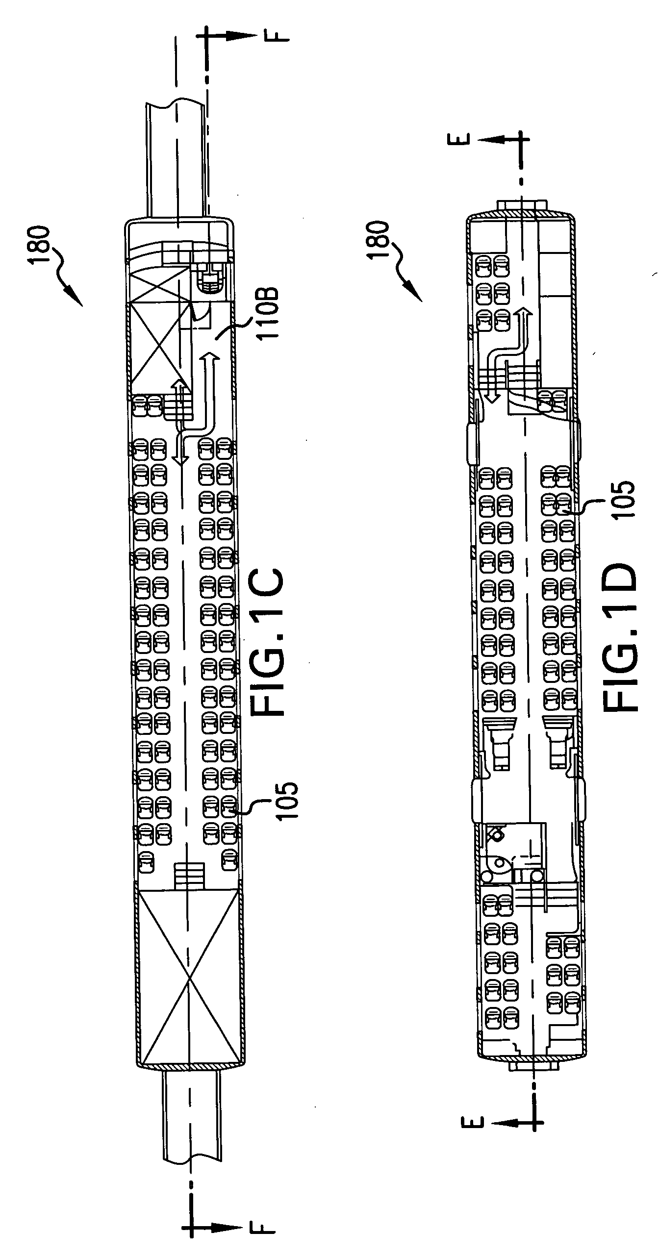
[0043]Referring to FIGS. 1A and 1B, in the invention, there is provided a multi-level cab car 100. The cab car 100 includes a lower passenger compartment level 120 that includes a plurality of passenger seats 105, an upper passenger compartment level 102 that includes a plurality of passenger seats 105, and a middle compartment level 125A, 125B with a plurality of passenger seats 105. The middle compartment has portions 125A, 125B at each end of the cab car 100. Front portion 125A has steps 130A that allow a passenger to move from the front portion 125A to the upper passenger compartment 102, and steps 130C that allow a passenger to move from the front portion125A to the lower passenger compartment 120. Rear portion 125B has steps 130B that allow a passenger to move from the rear portion 125B to the upper passenger compartment 102, and steps 130D that allow a passenger to move from the rear portion 125B to the lower passenger compartment 120. The front portion 125A ends at a first o...
third embodiment
[0053]In a third embodiment, as shown in FIG. 3, the front end of a cab car 300 has a left-side region (e.g., ⅓ the total width of the cab car) that is mostly slanted, a right-side region (e.g., ⅓ the total width of the cab car) that is mostly slanted, and a box-shaped middle region (e.g., ⅓ the total width of the cab car) having an upright lower portion that includes an entry / exit door, and a slanted top portion. The entry / exit door 340 is provided for enabling passengers to enter and exit the cab car 300 to an adjacent car, or for passage when the train is stationary, in case of emergency if the cab car 300 is the first car in the train. The top (roof) of the box-shaped structure 340 is slanted at a greater angle than the left and right portions of the front end. The slant of the top left- and right-side regions 310 of the front end may be set at a value between 30 degrees and 60 degrees, and the slant of the top portion above the entry / exit door 340 at the middle portion of the f...
fifth embodiment
[0066]FIG. 15 shows an underframe provided for the cab end crush zone according to the Push back coupler 1370, sliding sill 1520, shear bolts 1530 and end frame (fixed sill) 1540 can be readily seen in that figure.
[0067]In more detail, the crushable zone of the cab end is outboard of all occupied areas, with a vestibule wall separating the crushable zone from the passenger compartment, and with a metal skin that covers the crushable zone (to reduce wind resistance for a train that includes the cab car). A primary energy absorption system that includes the primary energy absorbers 1310 is located at the underframe level. A secondary energy absorption system that includes secondary energy absorbers 1320 is located above the underframe level at various levels behind the corner posts, in order to absorb energy and provide structure to help meet the post static requirements, and to act as guides to provide deflection of energy away from the passenger compartment.
[0068]Load is transferre...
PUM
 Abstract
Description
Claims
Application Information