Method for controlling LED-based backlight module

a backlight module and led-based technology, applied in the field of backlight modules, can solve the problems of notoriously inferior dynamic image display quality of lcds, and achieve the effect of lessening blur or flicker problems

Inactive Publication Date: 2007-11-15
VASTVIEW TECH
View PDF2 Cites 132 Cited by
  • Summary
  • Abstract
  • Description
  • Claims
  • Application Information

AI Technical Summary

Benefits of technology

[0007] Therefore, the major objective of the present invention is to control the lines of LEDs of a direct-lit backlight module within a frame time so as to achieve an impulse-type display effect from a hold-type LCD device due to the retardation pr

Problems solved by technology

Compared to the impulse-type display devices such as cathode ray tube (CRT) displays, the dynamic

Method used


Image

  • Method for controlling LED-based backlight module
  • Method for controlling LED-based backlight module
  • Method for controlling LED-based backlight module

Examples


third embodiment

[0030]FIGS. 4a, 4b, 4c, and 4d are a number of variations according to the present invention. They are very similar to those variations of the previous embodiment shown in FIGS. 3b, 3c, 3d, and 3e, respectively. The only difference lies in that, in FIGS. 4a, 4b, 4c, and 4d, driver control signals having asymmetric cycles are employed. As such, all odd-numbered or even-numbered lines are lighted for a period of time longer than when they are darkened; or all odd-numbered or even-numbered lines are darkened for a period of time longer than when they are lighted. Please note that, for this embodiment, it is possible to have all lines lighted or darkened at certain times. Please refer to the previous embodiment for details.

[0031]FIG. 5a is the driver control signal waveform diagram according to a fourth embodiment of the present invention. The present embodiment is actually an integration of the first embodiment (shown in FIGS. 2a, 2b, 2c) together with the gradual increase and decrease...

fifth embodiment

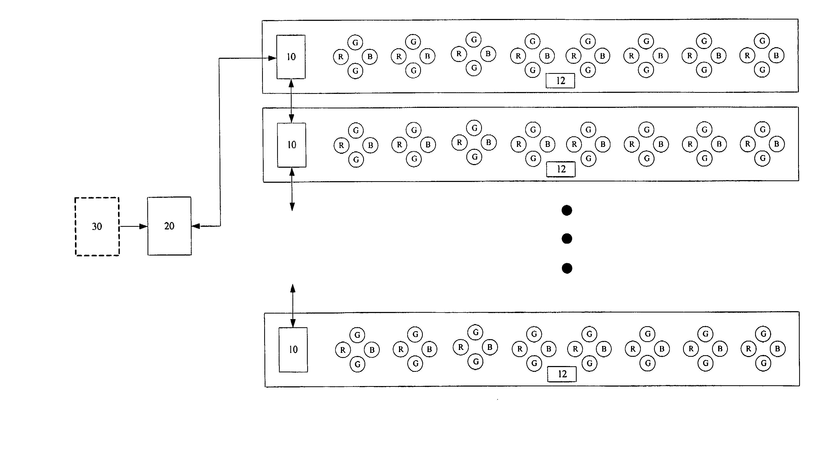
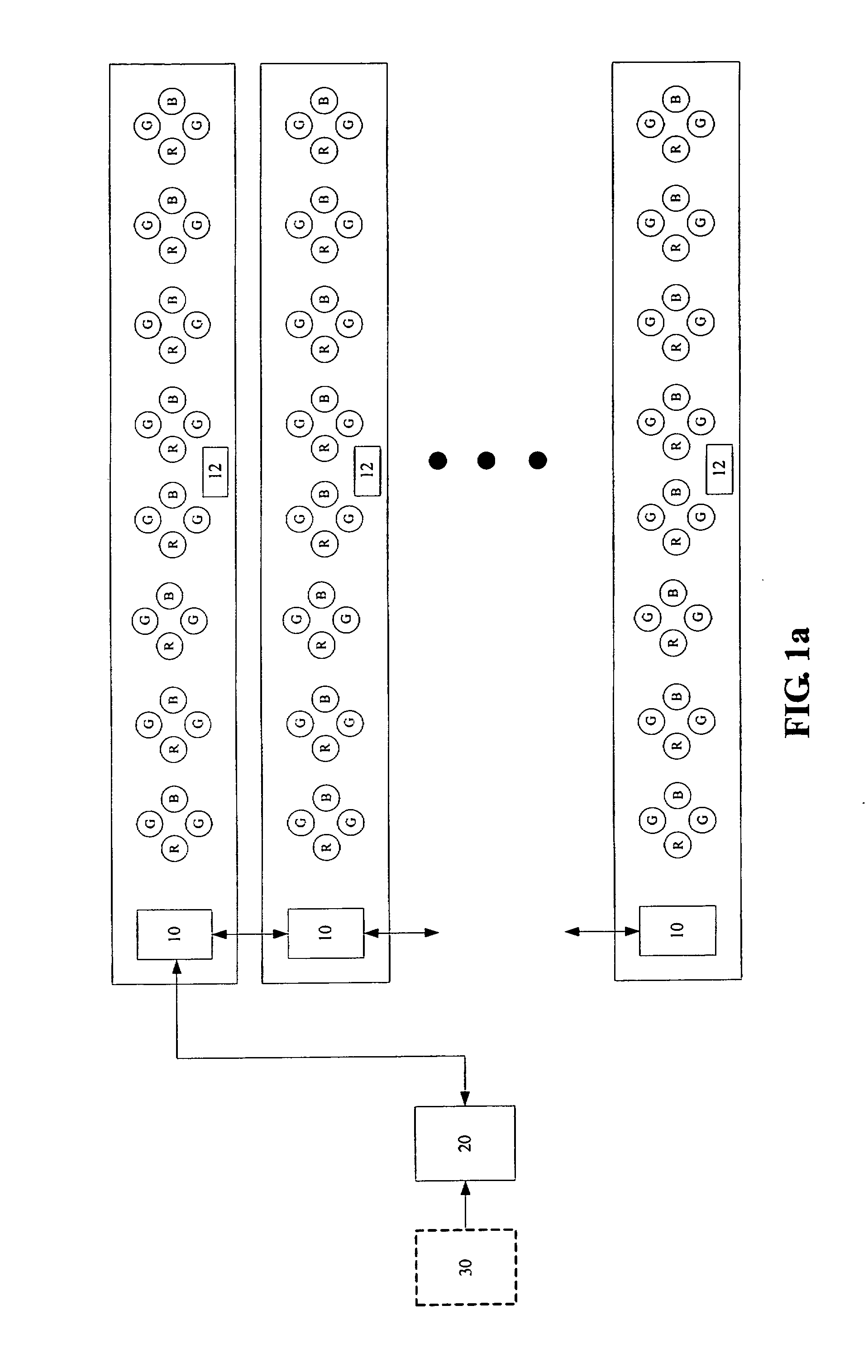
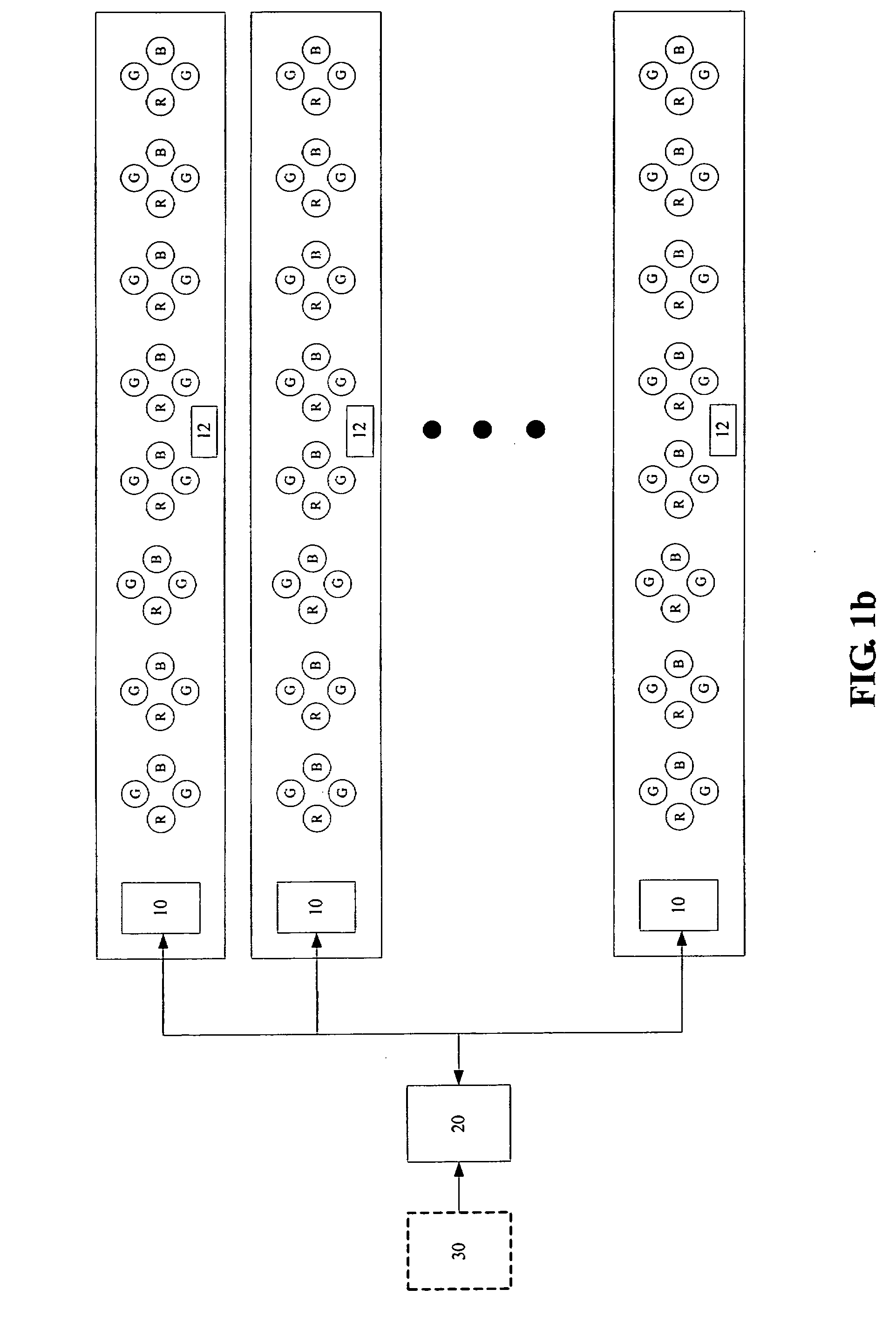
[0032] The previous embodiments all achieve a certain scanning effect for the LED-based, direct-lit backlight module. In other words, the lines of LEDs of the backlight module exhibit a line-by-line lighting (or darkening) behavior in a frame time in accordance with the scanning of the LCD device. FIG. 6a is the driver control signal waveform diagram according to the present invention, which exhibits a different behavior. In the present embodiment, the lines of LEDs are driven simultaneously by a driver control signal whose frequency is a multiple integral of the frame rate (e.g., 120 Hz, 180 Hz, and 240 Hz). In other words, the backlight module is actually “flashed” instead of “scanned.” Similarly, the duty cycle of the driver control signal can be adjusted (shown by the dashed line) for brightness control. FIGS. 6b and 6c are two variation of FIG. 6a, where the signal cycles are symmetric (in FIG. 6b) or asymmetric (in FIG. 6c).


PUM


Abstract

The method of the present invention turns off the line of LEDs of a backlight module behind the currently enabled scanline of a LCD device so that the transient behavior of the liquid crystal molecules are less obvious, thereby enhancing the dynamic response of the LCD device. For one type of embodiments, in accordance with the top-down scanning of the LCD device, the corresponding horizontal lines of the LEDs of the backlight module are turned off in a certain manner so that they exhibit a lighting (or, more precisely, darkening) pattern as if they are also “scanned” from top to down. For another type of embodiments, the horizontal lines of the LEDs of the backlight module are turned off and on simultaneously so that the backlight module actually “flashes” the LCD device.

Description

BACKGROUND OF THE INVENTION [0001] 1. Field of the Invention [0002] The present invention generally relates to backlight modules for display devices, and more particularly to a method for controlling the light emitting diodes of a direct-lit backlight module. [0003] 2. The Prior Arts [0004] Currently, most backlight modules for large-sized liquid crystal displays (LCDs) or LCD TVs adopt either cold cathode fluorescent lamps (CCFLs) or light emitting diodes (LEDs) as light source. As the CCFLs suffer potential environmental issues from the mercury vapor contained in the lamp tubes, while the LEDs have been advanced to provide superior switching speed, lighting efficiency, and cost, LEDs have become the main stream light source for LCDs. FIG. 7 is a schematic diagram showing a conventional LED-based, direct-lit backlight module. As illustrated, multiple LEDs are arranged in an array in front of a reflection plate. These LEDs could be white-light LEDs, or red-, green-, or blue-light LE...

Claims


Application Information

Patent Timeline
IPC IPC(8): H05B39/00
CPCG09G3/32G09G3/342G09G2310/0237G09G2310/024H05B33/0869G09G2320/0261G09G2320/0633G09G2320/064H05B33/0818G09G2310/08H05B45/22H05B45/327
Inventor SHEN, YUH-REN
Owner VASTVIEW TECH
Why Eureka
Try Eureka