System and method for regenerative energy control when multiple motors share a common power supply

Inactive Publication Date: 2007-11-15
HONEYWELL INT INC
View PDF8 Cites 10 Cited by
  • Summary
  • Abstract
  • Description
  • Claims
  • Application Information

AI Technical Summary

Benefits of technology

[0011] For instance, the DC bus linking each of the motors to the DC power supply may have a capacitive element configured to store the regenerative energy as it is transferred toward the power supply. The voltage across this capacitive element may be measured, and by monitoring these measurements, a power electronics controller may sense the

Problems solved by technology

In response, the power electronics controller may decrease the power factor of another mot

Method used


Image

  • System and method for regenerative energy control when multiple motors share a common power supply
  • System and method for regenerative energy control when multiple motors share a common power supply
  • System and method for regenerative energy control when multiple motors share a common power supply

Examples


Example

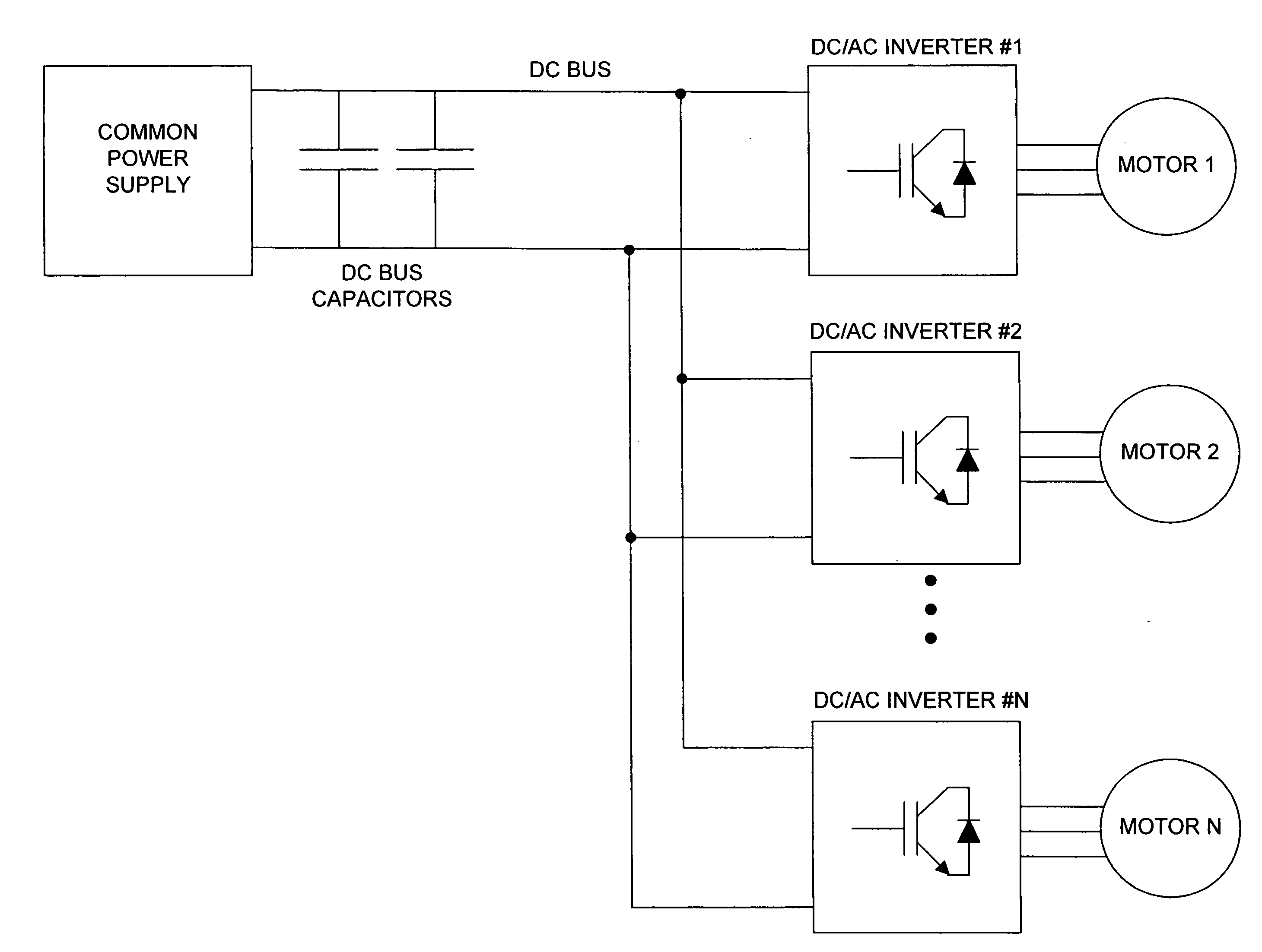
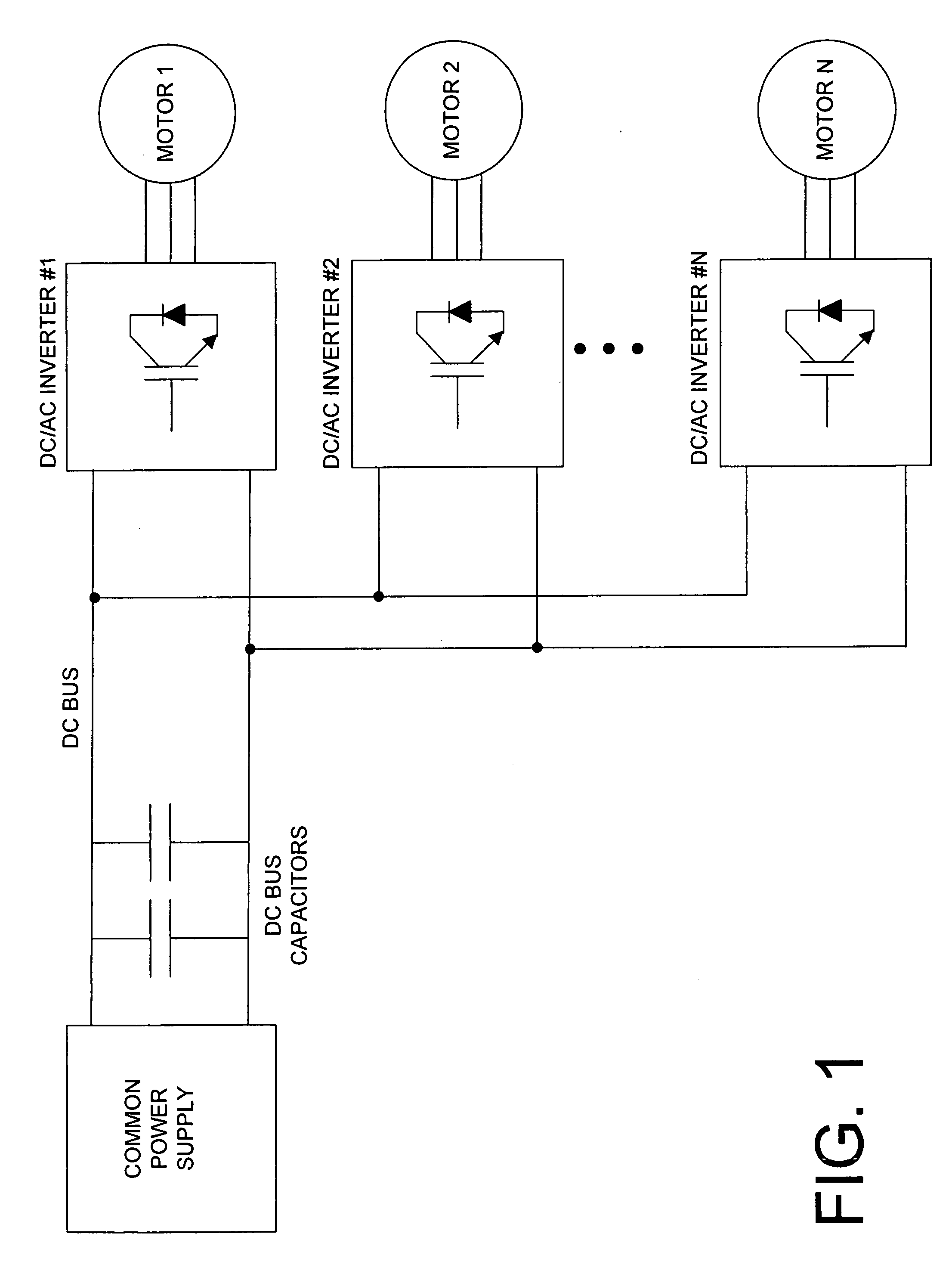
[0021] The present invention relates to a system in which multiple motors share a common DC power supply. FIG. 1 shows the basic configuration of such a system. As shown in FIG. 1, the power supply is connected to N motors (N≧2) via a DC power bus. The power supply may comprise any device configured to output DC power. Examples of the power supply include storage batteries, DC / DC converters, and AC / DC converters.

[0022] As shown in FIG. 1, the DC bus includes a capacitive element, such as one or more capacitors connected across the output terminals of the power supply. Furthermore, this figure shows that each of the N motors includes a DC / AC inverter. Each DC / AC inverter is responsible for receiving DC power from the bus and performing all necessary conversions to output a suitable AC signal to the motor. The DC / AC inverter operates under the control of a power electronics controller (not shown). By controlling the DC / AC inverter, the power electronics controller determines when the...


PUM


Abstract

When multiple motors (40) share a common DC power supply (10) via a bus (20), a system and method is provided for managing the effect of regenerative energy caused by a motor. The regenerative energy may be sensed, e.g., by a power electronics controller (50, 50′). In response, one or more of the other motors currently in operation may be controlled to operate according to a reduced power factor. Thus, the excess energy is consumed without adding any new components or increasing the amount of work performed in the system.

Description

STATEMENT REGARDING FEDERALLY SPONSORED RESEARCH OR DEVELOPMENT [0001] This invention was made with Government funding under contract N00019-02-C-3002 awarded by Joint Strike Fighter (JSF) Program. The Government has certain rights in the invention.FIELD OF THE INVENTION [0002] The present invention relates to a system and method for controlling regenerative energy when multiple motors share a common DC power supply, and more particularly, for controlling the power factor of a motor to dissipate regenerative energy created by another motor. In this manner the system is capable of maintaining the balance of energy within safe operating parameters. BACKGROUND OF THE INVENTION [0003] A simplified configuration of a system in which multiple motors share a common DC power supply is illustrated in FIG. 1. As shown in this figure, each of the motors is connected to the DC power supply via a DC bus. FIG. 1 further shows that the DC bus includes a capacitive element, e.g., one or more capaci...

Claims


Application Information

Patent Timeline
IPC IPC(8): H02P3/00
CPCH02P5/74H02P23/06H02P23/0081H02P23/26
Inventor LLOYD, SONNY L.YALDIZCIYAN, DIKRANMORCOV, NICOLAE A.
Owner HONEYWELL INT INC
Why Eureka
Try Eureka