
Parallel running control apparatus for inverter generators

Active Publication Date: 2012-11-22
HONDA MOTOR CO LTD
View PDF15 Cites 22 Cited by
  • Summary
  • Abstract
  • Description
  • Claims
  • Application Information

AI Technical Summary

Benefits of technology

[0006]Further, in case of a parallel running control for single-phase two-wire inverter generators, if one of the generators is stopped during the parallel running operation, since the output from the generator is single-phase, it does not cause a phase fluctuation that adversely influences upon a load. However, in a parallel running control apparatus for three-phase inverter generators, since each phase of the power outputs from the generators to be supplied to a load is offset by 120 degrees, if a reference generator is stopped during the parallel running operation, it disadvantageously increases the probability to cause a phase fluctuation of the power output. As a resu

Problems solved by technology

However, for three-phase alternating current inverter generators, since it is required to synchronize each phase and each voltage amplitude of a three-phase alternating current of one generator with those of other generator, it is difficult to run three-phase alternating current inverter generators in parallel from the teaching of the reference.
However, in a parallel running control apparatus for three-phase inverter generators, since each phase of the power outputs from the generators to be supplied to a load is offset by 120 degrees, if a reference generator is stopped during the parallel running operation, it disadvantageously increases the probability to cause a phase fluctuation of the power output.
As a result, a power factor of the load, e.g., a three-phase motor, decreases and the motor becomes unable to generate a normal rotating magnetic field and therefore, unable to operate the load sufficiently.

Method used


Image

  • Parallel running control apparatus for inverter generators
  • Parallel running control apparatus for inverter generators
  • Parallel running control apparatus for inverter generators

Examples


first embodiment

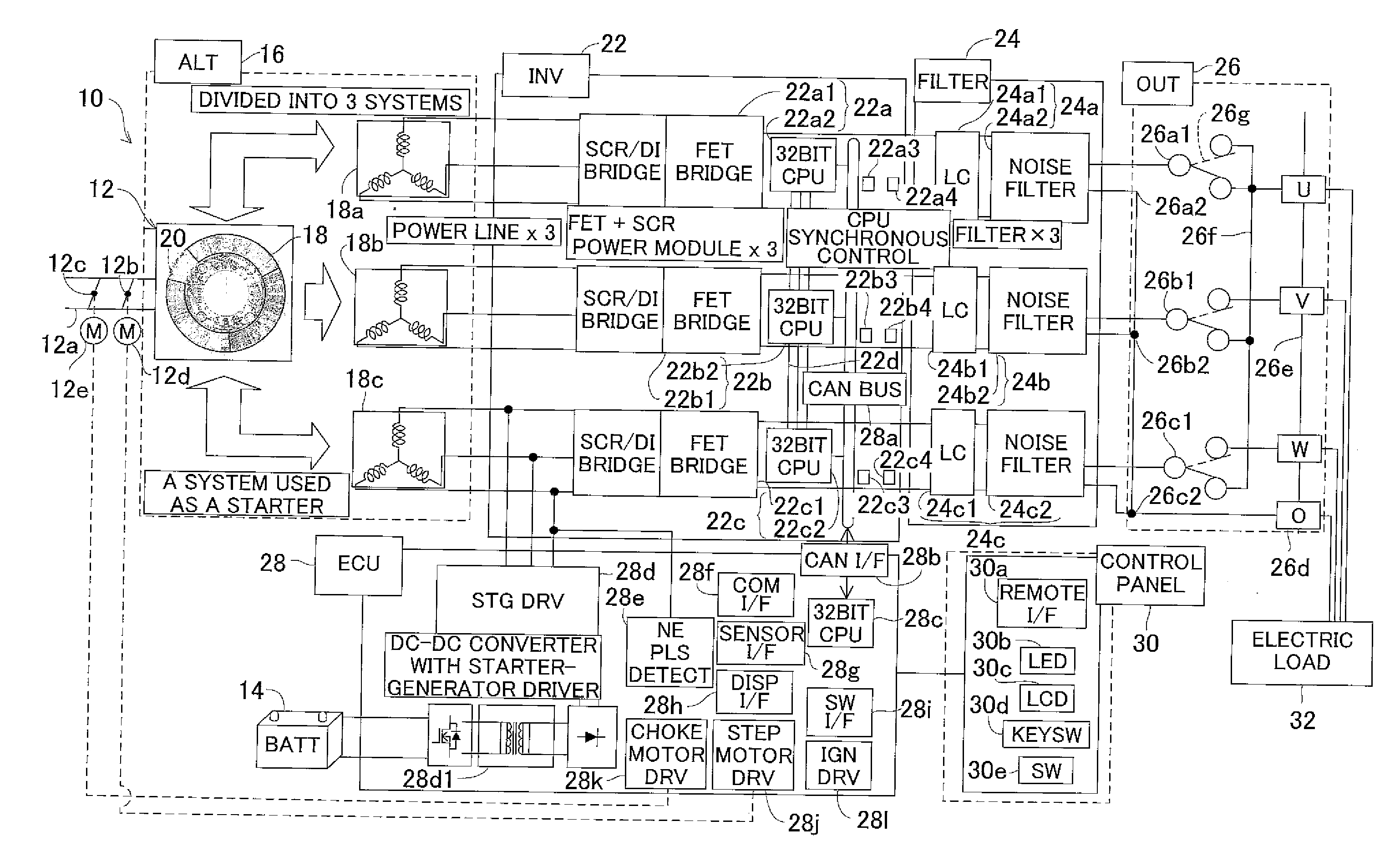
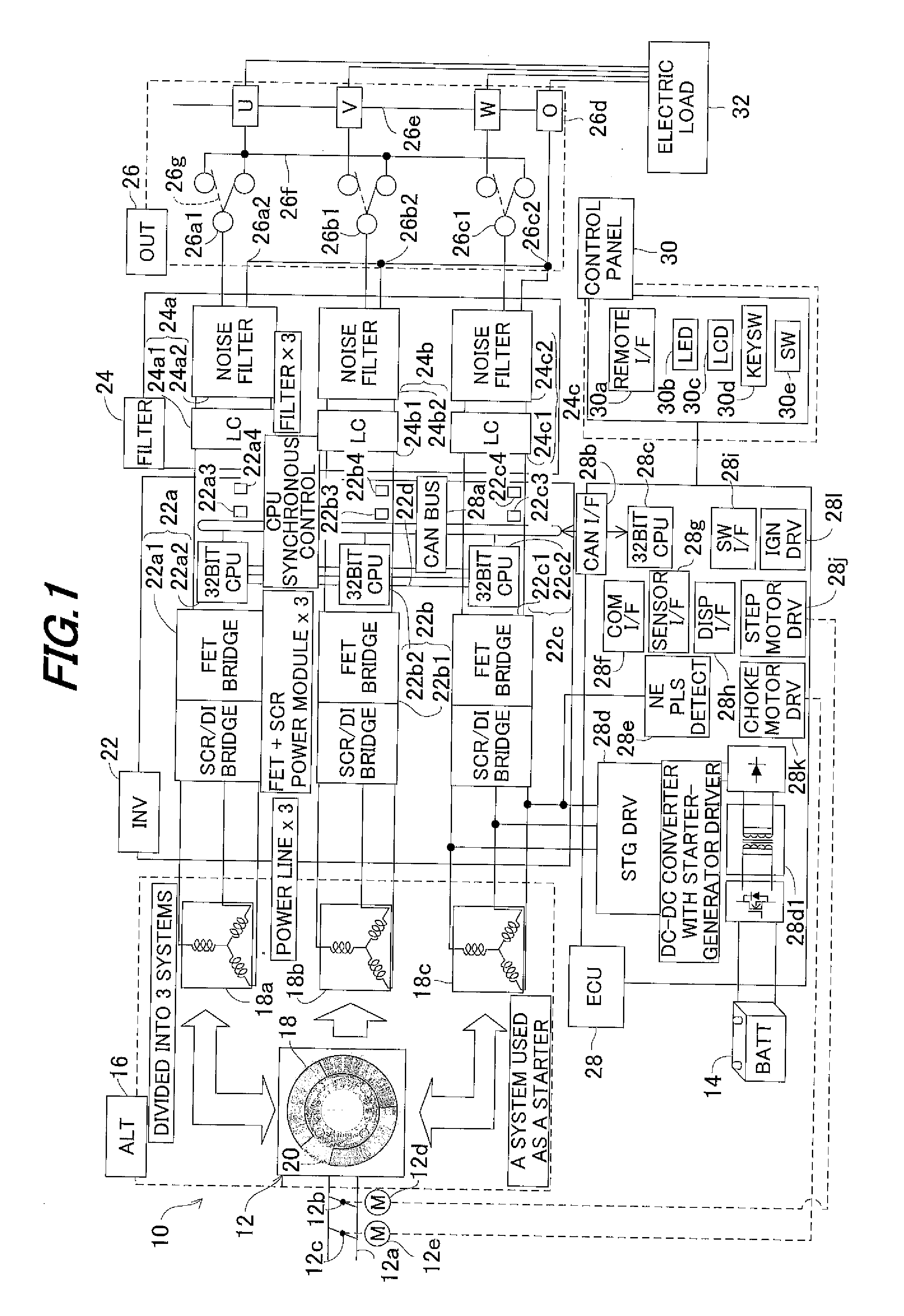
[0030]FIG. 1 is an overall block diagram showing a parallel running control apparatus for inverter generators according to the invention.

[0031]In FIG. 1, symbol 10 designates an inverter generator. The generator 10 is equipped with an internal combustion engine 12 and has a rated output of about 5 kW (AC (alternating current) 100V, 50A). The engine 12 is an air-cooled, spark-ignition gasoline engine.

[0032]A throttle valve 12b and choke valve 12c are installed in an air intake pipe 12a of the engine 12. The throttle valve 12b is connected to a throttle motor (composed of a stepper motor) 12d, and the choke valve 12c is connected to a choke motor (also composed of a stepper motor) 12e.

[0033]The engine 12 is equipped with a battery 14 whose rated output is about 12V. When power is supplied from the battery 14, the throttle motor 12d and choke motor 12e respectively drive the throttle valve 12b and choke valve 12c to open and close. The engine 12 has an alternator section (shown as “AL...

second embodiment

[0107]The parallel running control apparatus for inverter generators according to this invention will now be explained.

[0108]FIG. 17 is a flowchart explaining an operation of CPUs 22a2, 22b2, 22c2 (first, second, third controllers), especially the CPU 22a2 of the slave generator 10A during a parallel running operation of two inverter generators according to the second embodiment of this invention.

[0109]In this embodiment, when a phase difference between the AC output from own (subject) second inverter 22b or own third inverter 22c and a corresponding synchronous signal becomes greater than or equal to the predetermined value (FIG. 14, S18), the first controller 22a2 of the generator 10A is configured to execute the self-sustained running control by communicating to the second and third controllers 22b2, 22c2.

[0110]Similar to the processing from S10 to S18 in FIG. 14 of the first embodiment, the program begins at S100, in which the parallel running operation with the generator 10B is...


PUM


Abstract

In a parallel running control apparatus for inverter generator A having first, second and third inverters adapted convert alternating current outputted from windings wound around an alternator into direct / alternating current by driving switching elements, and CPUs to control turning ON / OFF of the switching elements, it is configured so that the generator A runs in parallel with at least one inverter generator B, which is configured to be same as the inverter generator A, to output a three-phase alternating current, and one of the CPU determines that the generator B was stopped when at least one of phase differences between a phase of an output from the first inverter and phases of outputs from the second and third inverters becomes greater than or equal to a predetermined value.

Description

BACKGROUND OF THE INVENTION[0001]1. Technical Field[0002]Embodiments of the invention relate to a parallel running control apparatus for inverter generators, particularly to a control apparatus that can run inverter generators outputting a three-phase alternating current in parallel[0003]2. Background Art[0004]Conventionally, there is a well-known technique for a parallel running control apparatus for inverter generators, as taught, for example, by Japanese Patent No. 2996542. In the reference, a phase and a voltage amplitude of a single-phase two-wire inverter generator are synchronized with the those of other single-phase two-wire inverter generators, such that the generators are run in parallel.SUMMARY[0005]Thus the reference discloses running single-phase two-wire inverter generators in parallel by synchronizing their phase and voltage amplitude. However, for three-phase alternating current inverter generators, since it is required to synchronize each phase and each voltage ampl...

Claims


Application Information

Patent Timeline
IPC IPC(8): H02J3/46
CPCH02J3/40H02P9/02H02P25/22
Inventor HASHIMOTO, SHOJIYAMAMURA, YOICHI
Owner HONDA MOTOR CO LTD
Learn More