Switching power supply

Active Publication Date: 2017-01-19
FUJI ELECTRIC CO LTD
View PDF2 Cites 17 Cited by
  • Summary
  • Abstract
  • Description
  • Claims
  • Application Information

AI Technical Summary

Benefits of technology

[0038]In the switching power supply configured as described above, the ON time increasing circuit force-increases the ON time Ton of the switching element when the OFF time Toff of the switching element is less than a prescribed value in phase angle regions in which the instantaneous value of the input voltage Vin is low (low voltage phase regions). This makes it possible to prevent the current supplied to the inductance element from decreasing in the low phase regions of the input voltage, thereby preventing decreases in the power factor.
[0039]Moreover, when the error voltage Verr is greater than a prescribed value (that is, when it is determine

Problems solved by technology

However, in the technology disclosed in Patent Document 3, the ON time Ton of the switching element is force-increased when the OFF time Toff is too low.
Therefore, during heavy loading states in which the input voltage Vin is low and the ON time Ton of the switching element is set to a relatively high value, the waveform of the current flowing through the inductance element may become significantly disrupted by any noise that enters the control circuit.
Any noise input to this ZCD terminal may therefore result in a zero-current state being erroneously detected before the induct

Method used


Image

  • Switching power supply
  • Switching power supply
  • Switching power supply

Examples


Example

[0048]Next, a switching power supply according to an embodiment of the present invention will be described with reference to figures.

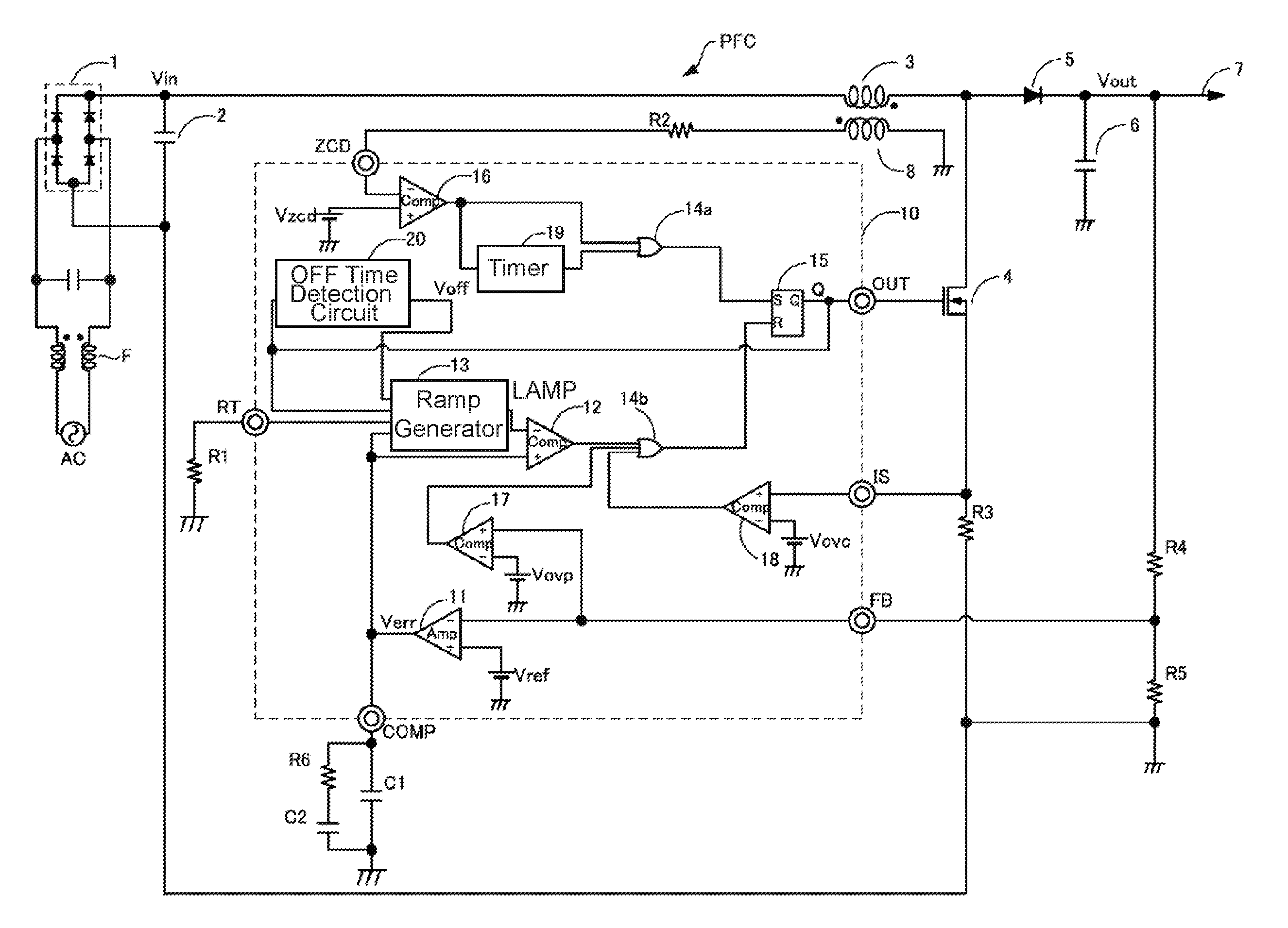
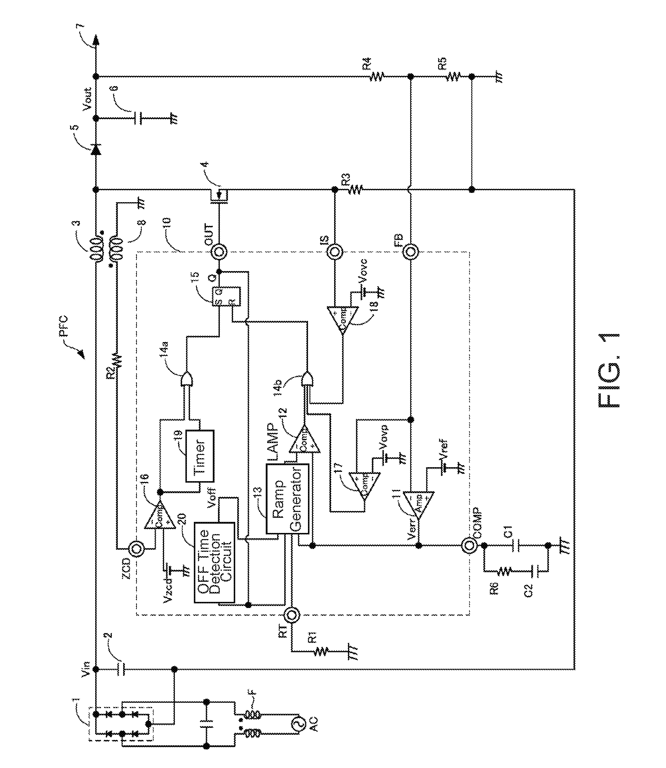
[0049]FIG. 1 schematically illustrates a configuration of a switching power supply (power factor correction converter) PFC according to this embodiment of the present invention. As illustrated in FIG. 1, a rectifier circuit 1 rectifies an AC voltage applied from an input power source AC via an input filter F and inputs the rectified voltage to the switching power supply PFC. The input power source AC is a commercial AC power source of a 100V system or 220V system, and the rectifier circuit 1 is a diode bridge circuit, for example.

[0050]The switching power supply PFC includes an inductance element 3 that is connected to the rectifier circuit 1 and a switching element 4 that, when switched ON, forms a current path to the rectifier circuit 1 via the inductance element 3. The switching power supply PFC also includes a diode 5 that forms a current path betw...


PUM


Abstract

The switching element is turned ON and OFF according to when the current flowing through the inductance element becomes equal to zero and according to an amplified error voltage between the output voltage and a target output voltage. More particularly, the OFF time of the switching element is calculated, and when the OFF time is less than a prescribed value, the ON time of the switching element is increased. Moreover, the amount by which the ON time of the switching element is increased is reduced if the error voltage if greater than a prescribed value.

Description

BACKGROUND OF THE INVENTION[0001]Technical Field[0002]The present invention relates to a switching power supply that maintains a high power factor when a high voltage is input and also maintains stable operation when a low voltage is input.[0003]Background Art[0004]One type of switching power supply is a step-up chopper-type power factor correction (PFC) converter, in which an inductance element is used to create an input current proportional to an input voltage while generating a stable DC output voltage. This type of device offers a number of advantages, such as being small in size, having a high efficiency, and being low in cost.[0005]This type of switching power supply typically includes an inductance element that is connected to an AC input power source via a rectifier circuit and a switching element that, when switched ON, forms a current path to the AC input power source via the inductance element. This type of switching power supply also typically includes a voltage output c...

Claims


Application Information

Patent Timeline
IPC IPC(8): H02M3/335H02M1/14H02M1/08H02M1/42
CPCH02M3/33507H02M1/42H02M2001/0009H02M1/08H02M1/143H02M1/083H02M1/4225Y02B70/10Y02P80/10H02M1/0022H02M1/0025H02M1/0064H02M1/0009H02M3/156
Inventor SUGAWARA, TAKATO
Owner FUJI ELECTRIC CO LTD
Why Eureka
Try Eureka