Proximity sensor device and method with improved indication of adjustment

a proximity sensor and indication technology, applied in the field of electronic devices, can solve the problems of requiring a significant level of attention and dexterity, and non-trivial training of nave users in its use, and achieve the effects of convenient user interface navigation, easy adjustment, and improved system usability

Inactive Publication Date: 2007-11-15
SYNAPTICS INC
View PDF23 Cites 116 Cited by
  • Summary
  • Abstract
  • Description
  • Claims
  • Application Information

AI Technical Summary

Benefits of technology

[0008] The present invention provides a proximity sensor device and method that facilitates improved system usability. Specifically, the proximity sensor device and method provide the ability for a user to easily cause an adjustment in an electronic system using a proximity sensor device as a user interface. For example, it can be used to facilitate user interface navigation, such as scrolling. As another example, it can be used to facilitate value adjustments, such as changing a device parameter. To facilitate adjustment, the embodiments of the present invention provide a proximity sensor device that is adapted to indicate adjustment in a first way responsive to object motion in both of two opposite directions along a path proximate a first sensing region of the touch sensor device. This facilitates use of the proximity sensor device by a user to indicate adjustments to an electronic device. It is particularly useful for indicating continuing adjustments, for example, to facilitate scrolling through a large document. In those cases the continued adjustment can be indicated by object motion back and forth along the path. This allows a user to con

Problems solved by technology

However, using them with different input devices, particularly proximity sensor devices, can require a significant level of attention and dexterity.
H

Method used


Image

  • Proximity sensor device and method with improved indication of adjustment
  • Proximity sensor device and method with improved indication of adjustment
  • Proximity sensor device and method with improved indication of adjustment

Examples


Embodiment Construction

[0017] The following detailed description is merely exemplary in nature and is not intended to limit the invention or the application and uses of the invention. Furthermore, there is no intention to be bound by any expressed or implied theory presented in the preceding technical field, background, brief summary or the following detailed description.

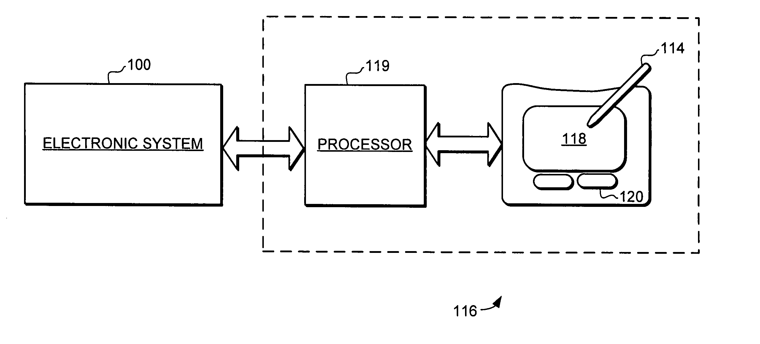
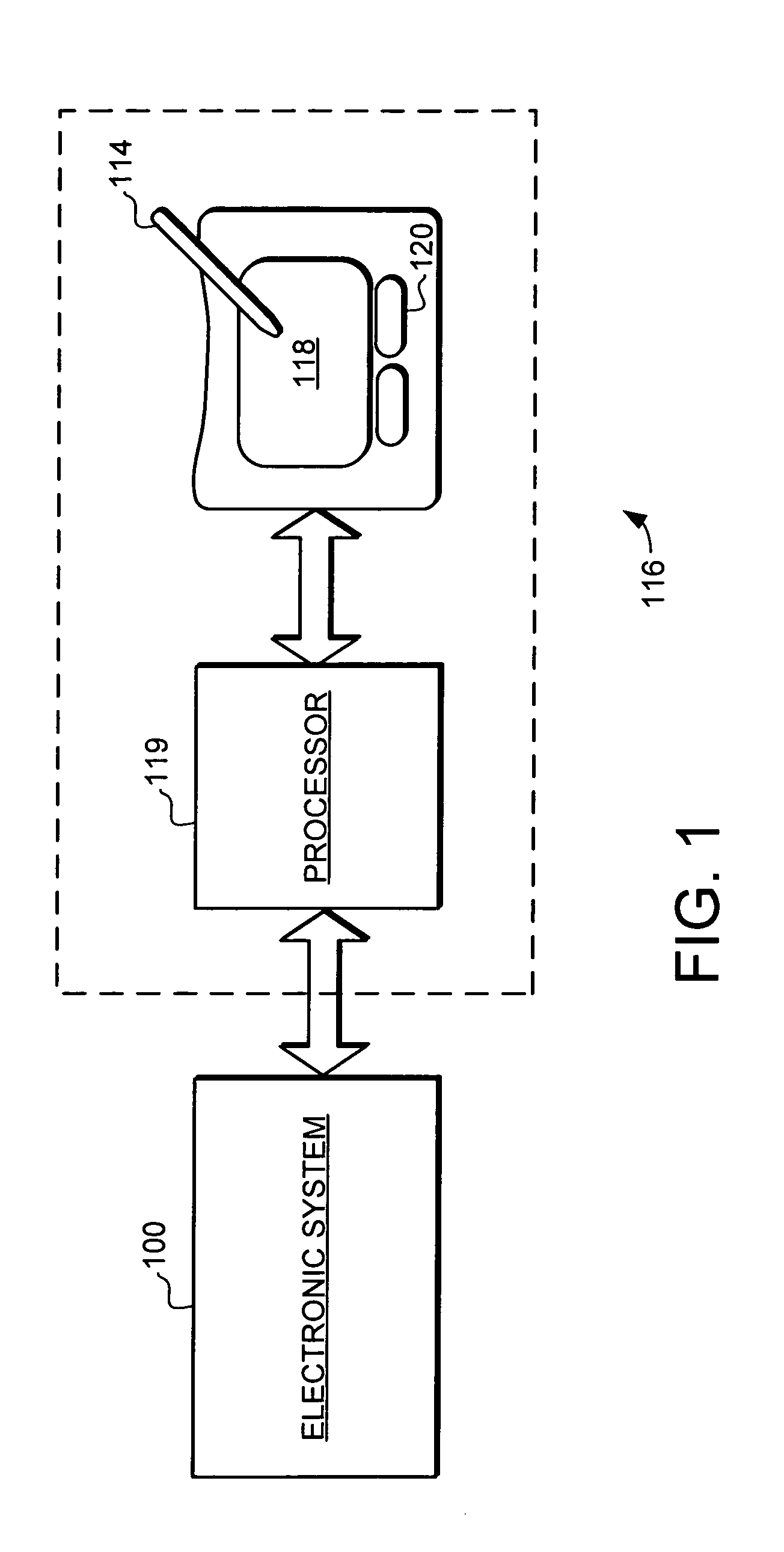
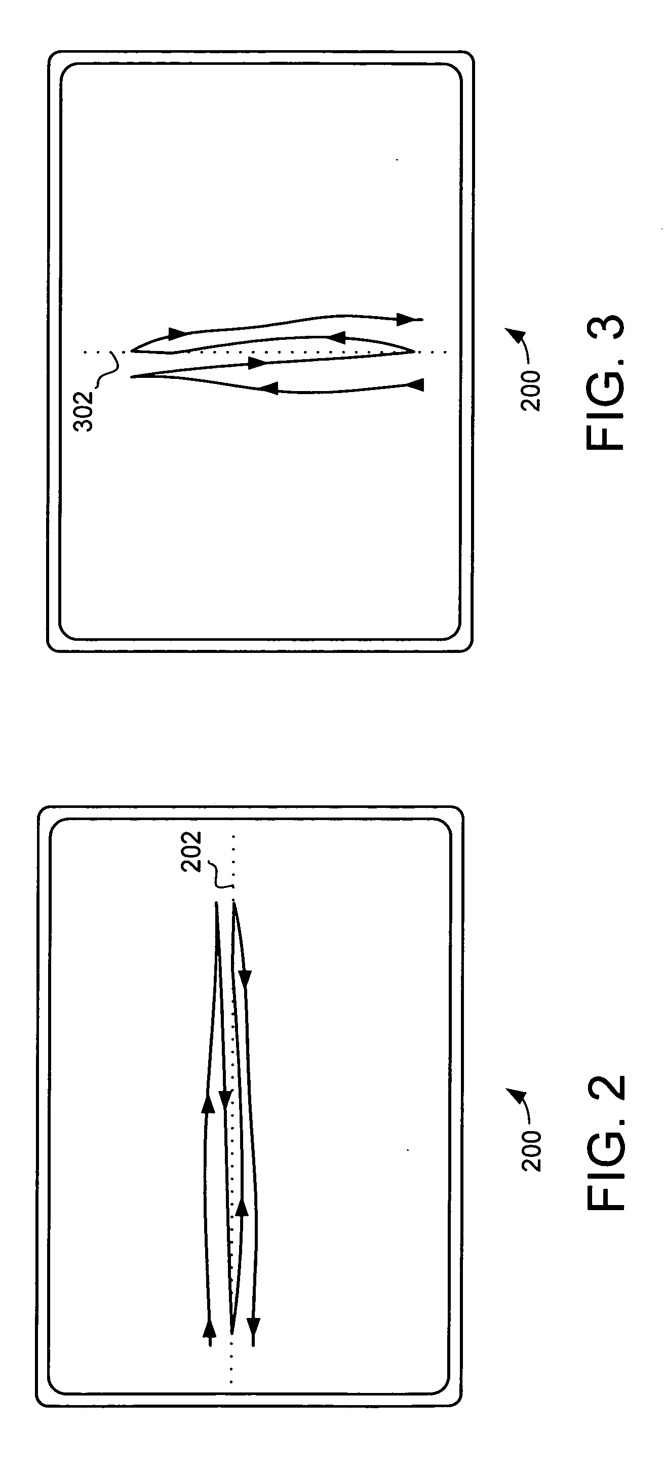
[0018] The present invention provides a proximity sensor device and method that facilitates improved system usability. Specifically, the proximity sensor device and method provide the ability for a user to easily cause adjustments in an electronic system using a proximity sensor device as a user interface. For example, it can be used to facilitate user interface navigation, such as scrolling. As another example, it can be used to facilitate value adjustments, such as changing a device parameter. To facilitate usability, the embodiments of the present invention provide a touch sensor device that is adapted to indicate adjustment in a firs...


PUM


Abstract

A proximity sensor device and method is provided that facilitates improved system usability. Specifically, the proximity sensor device and method provide the ability for a user to easily cause adjustments in an electronic system using a proximity sensor device as a user interface. For example, it can be used to facilitate user interface navigation, such as scrolling. As another example, it can be used to facilitate value adjustments, such as changing a device parameter. To facilitate adjustment, the embodiments of the present invention provide a proximity sensor device that is adapted to indicate adjustment in a first way responsive to object motion in both of two opposite directions along a path proximate the touch sensor device. This facilitates use of the proximity sensor device by a user to indicate adjustments to an electronic device, and is particularly useful for indicating continuing adjustments.

Description

FIELD OF THE INVENTION [0001] This invention generally relates to electronic devices, and more specifically relates to proximity sensor devices. BACKGROUND OF THE INVENTION [0002] Proximity sensor devices (also commonly called touch pads or touch sensor devices) are widely used in a variety of electronic systems. A proximity sensor device typically includes a sensing region, often demarked by a surface, which uses capacitive, resistive, inductive, optical, acoustic and / or other technology to determine the presence, location and / or motion of one or more fingers, styli, and / or other objects. The proximity sensor device, together with finger(s) and / or other object(s), can be used to provide an input to the electronic system. For example, proximity sensor devices are used as input devices for larger computing systems, such as those found integral within notebook computers or peripheral to desktop computers. Proximity sensor devices are also used in smaller systems, including: handheld s...

Claims


Application Information

Patent Timeline
IPC IPC(8): G09G5/00
CPCG06F3/04883G06F3/0485
Inventor HUIE, MARKCHENG, WENDY
Owner SYNAPTICS INC
Why Eureka
Try Eureka