Broadcast Receiving Apparatus

Inactive Publication Date: 2007-11-15
PANASONIC CORP
View PDF0 Cites 17 Cited by
  • Summary
  • Abstract
  • Description
  • Claims
  • Application Information

AI Technical Summary

Benefits of technology

[0009] According to the present invention, a broadcast receiving apparatus can be provided

Problems solved by technology

In the case of a portable terminal that allows viewing of such TV broadcasting, TV viewing is not possible if the terminal moves bey

Method used


Image

  • Broadcast Receiving Apparatus
  • Broadcast Receiving Apparatus
  • Broadcast Receiving Apparatus

Examples


embodiment 1

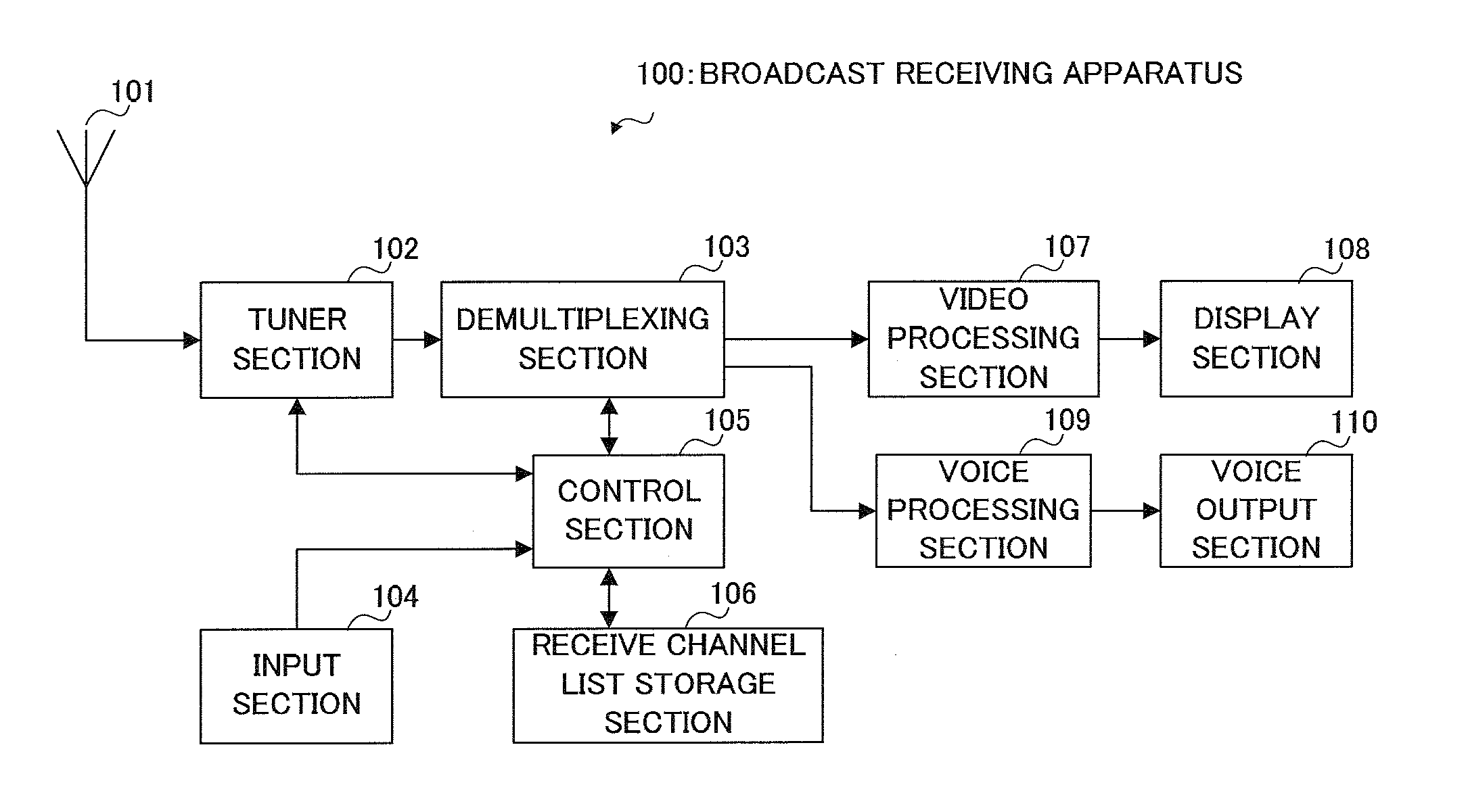
[0019] In Embodiment 1 of the present invention, a digital broadcast receiving apparatus is taken as an example. First, a brief outline of terrestrial digital broadcasting will be given. In terrestrial digital broadcasting, it is planned to provide a data broadcasting service by allocating one of 13 divisions of a channel band (6 MHz) (one segment). This data broadcasting service is called partial reception broadcasting. The amount of information transmitted in one segment is extremely small, and program information and so forth for only ten programs at the most can be included. PSI (Program Specific Information) and SI (Service Information) are known as program information. PSI is information necessary for selecting a desired program, while SI comprises various kinds of stipulated information for making program selection more convenient, including EPG (Electronic Program Guide) related information such as program names, broadcasting station names, and so forth.

[0020] Also, in terr...

embodiment 2

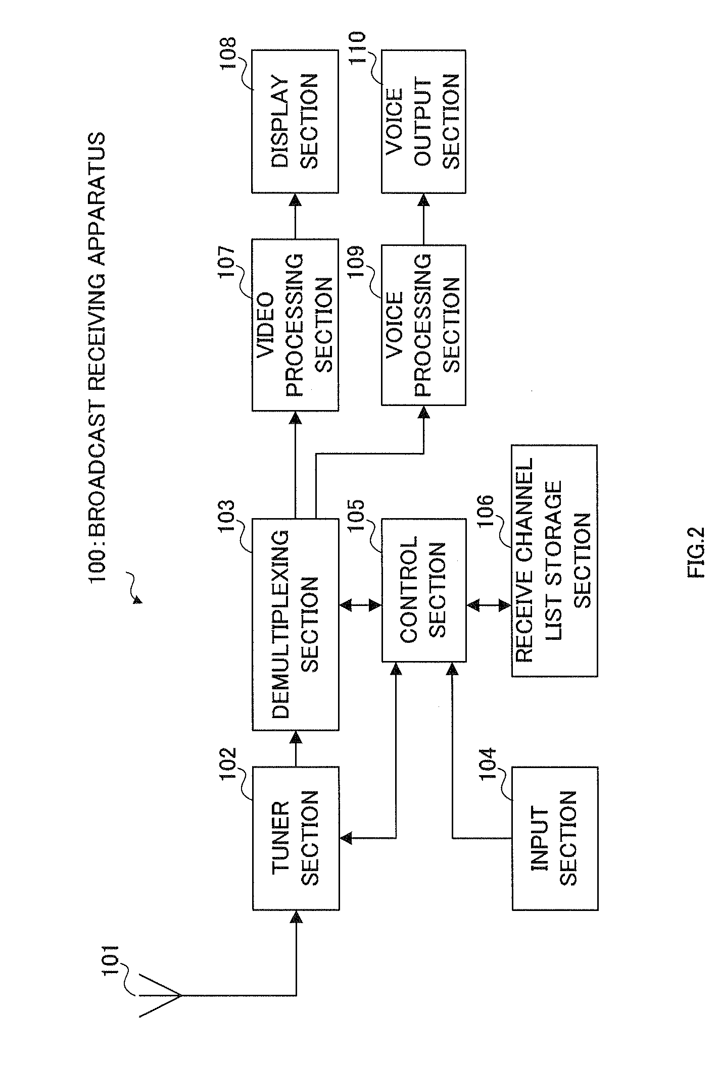
[0053] In Embodiment 1, processing when a broadcast receiving apparatus moves beyond a broadcast area after being started up was described. In Embodiment 2 of the present invention, processing when a broadcast receiving apparatus is started up will be described. The configuration of a digital broadcast receiving apparatus according to this embodiment is the same as in FIG. 2 and FIG. 3, and therefore FIG. 2 and FIG. 3 will be referred to in the description.

[0054] Each time broadcasting station determination and a channel list setting change are performed in channel list determination processing (corresponding to ST134 in FIG. 5), receive channel list storage section 106 shown in FIG. 2 and FIG. 3 stores a corresponding remote controller number together with current channel list identification information as a last channel list. Here, a remote controller number is cited as an example, but a 3-digit number or service ID may also be used, or any information capable of indicating a cha...

embodiment 3

[0060] In Embodiment 3 of the present invention, a case in which broadcast wave reception ceases to be possible during TV playback will be described. The configuration of a digital broadcast receiving apparatus according to this embodiment is the same as in FIG. 2 and FIG. 3, and therefore FIG. 2 and FIG. 3 will be referred to in the description.

[0061]FIG. 8 is a flowchart showing the procedure of abnormal reception avoidance processing during TV playback of a broadcast receiving apparatus according to Embodiment 3 of the present invention. In ST161 in FIG. 8, it is determined whether a broadcast wave is being received normally and video and voice are being played back. If it is determined that a broadcast wave is being received normally (YES) abnormal reception avoidance processing is terminated. On the other hand, if it is determined that a broadcast wave is not being received normally, such as when the reception state is poor, video or voice underflow has occurred, or playback h...


PUM


Abstract

A broadcast receiving apparatus capable of automatically switching channel lists without increasing the apparatus scale nor increasing the power consumption. In this apparatus, a received channel list storing part (106) stores a plurality of channel lists corresponding to a plurality of different broadcast areas, and a switched station selection control part (121) uses a currently set first channel list of the plurality of channel lists to select a station. If this station selection is failed, then the switched station selection control part (121) switches the currently set channel list to a second channel list and uses the second channel list channels to perform a station selection.

Description

TECHNICAL FIELD [0001] The present invention relates to a broadcast receiving apparatus installed in a portable terminal. BACKGROUND ART [0002] Portable terminals such as mobile phones enabling TV viewing are becoming increasingly popular, and if a user can receive TV waves while moving, or at the user's destination, it is possible to view TV without restrictions as to location. [0003] In television, a list called a channel list that corresponds to a broadcast area is generally created by means of a channel search, or provided beforehand, and this channel list contains channels that can be received in a particular area together with associated numbers specifying the channels. [0004] In the case of a portable terminal that allows viewing of such TV broadcasting, TV viewing is not possible if the terminal moves beyond a broadcast area since the terminal does not have a channel list corresponding to the broadcast area to which the terminal moves. [0005] Thus, the invention disclosed in...

Claims


Application Information

Patent Timeline
IPC IPC(8): H04N5/445H04N5/50H04B1/16H04N5/44
CPCH04N5/4401H04N5/50H04N7/163H04N21/4126H04N21/4821H04N21/42204H04N21/4345H04N21/4383H04N21/41407H04N21/426H04N21/41265
Inventor NISHI, TATSUYA
Owner PANASONIC CORP
Why Eureka
Try Eureka