
Method and circuit thereof for smapling/holding signal

a signal and circuit technology, applied in the field of signal sampling/holding, can solve problems such as inevitability, and achieve the effect of avoiding sampling switch noise, reducing sampling noise, and increasing circuit area and power consumption

Inactive Publication Date: 2005-10-27
SUNPLUS TECH CO LTD
View PDF4 Cites 0 Cited by
  • Summary
  • Abstract
  • Description
  • Claims
  • Application Information

AI Technical Summary

Benefits of technology

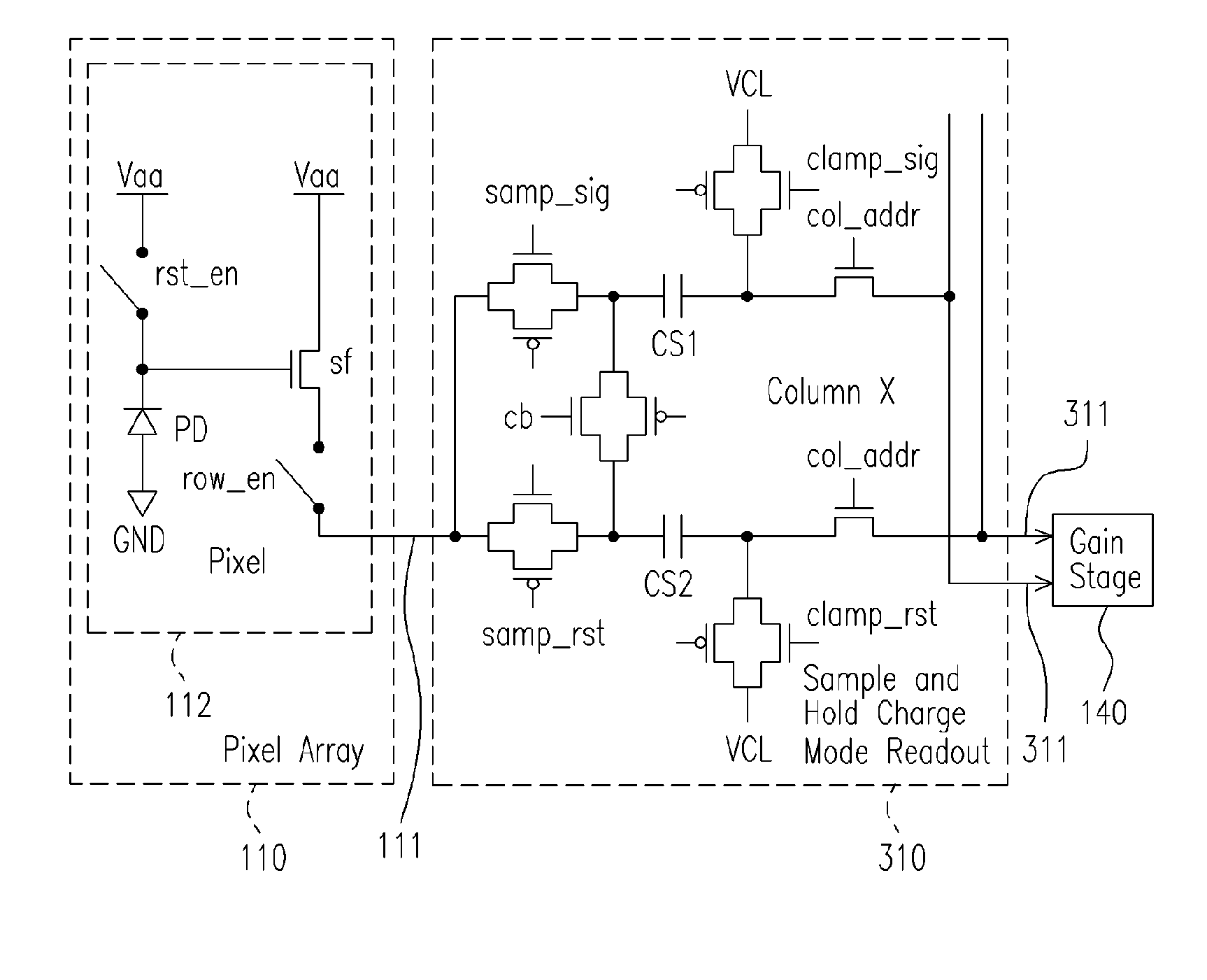
[0011] In the light of the above description, the present invention is directed to a method of signal sampling / holding, for eliminate sampled signal noise caused by charge injection when sensing switch is switched.
[0012] The present invention is also directed to a circuit of signal sampling / holding, using simplified method steps, fixed circuit area and similar power consumption, sampled signal noise caused by charge injection when switching the sensing switch is avoided.
[0013] The present invention is also directed to a method of signal sampling / holding, using simplified circuit and timing control technique, fixed circuit area and similar power consumption, sampled signal noise caused by charge injection when switching the sensing switch is avoided.
[0022] According to the above description, sampling noise is lowered with the timing control technique in the present invention without increasing circuit area and power consumption. Since signal sampling switch noise is randomly generated, which is hardly to be filtered out in back-end circuit, it is more efficient to be removed in front-end circuit. Disconnecting the reference voltage before switching the sampling switch avoids sampling switch noise, such that S / N ratio is higher as desired.

Problems solved by technology

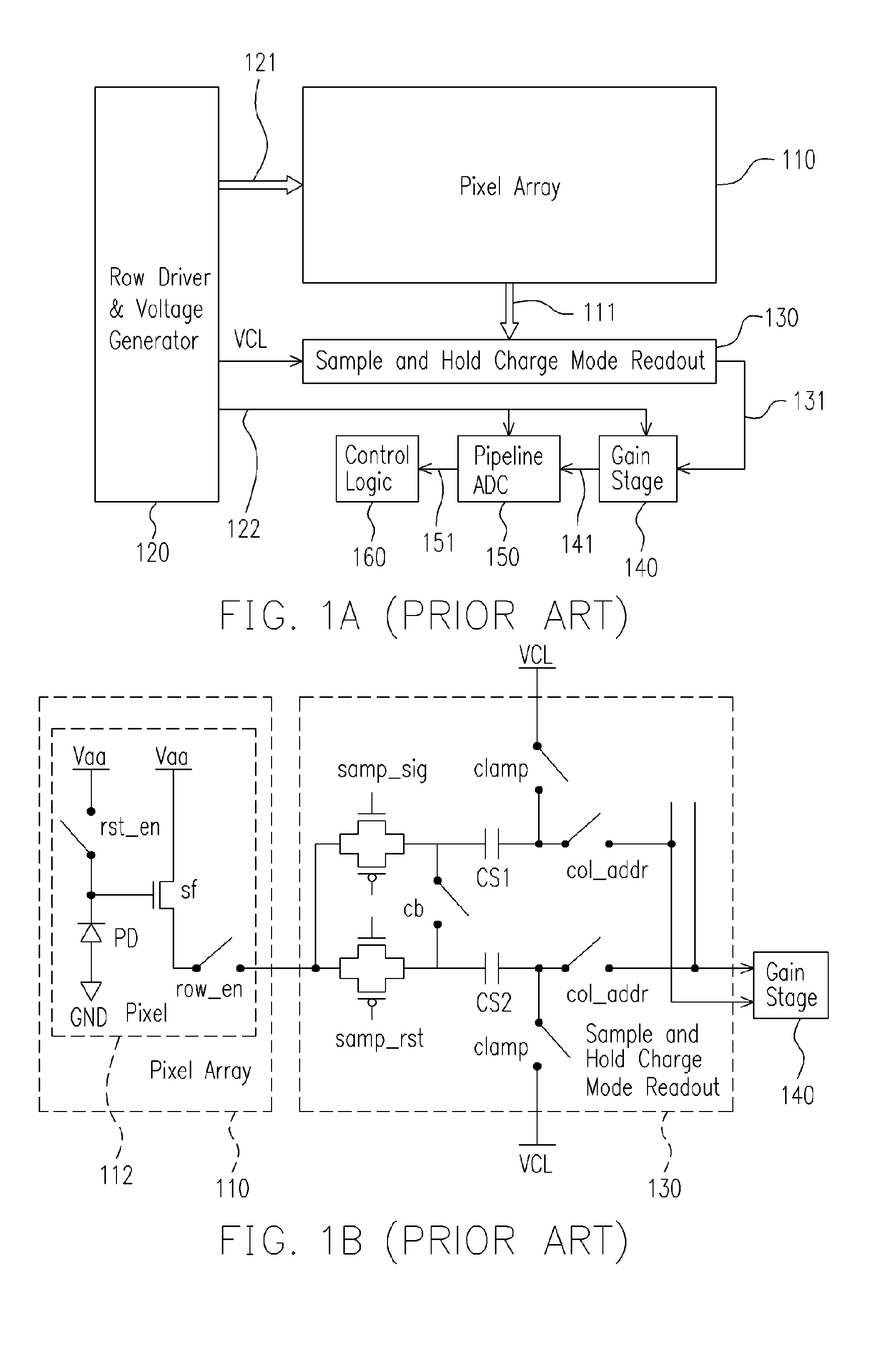
Signal sampling / holding is one of the major issues of electronic circuits.
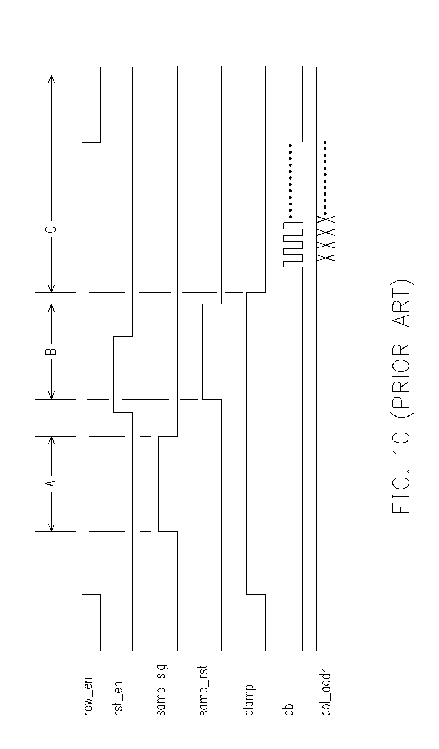
When period A for sampling pixel signal value is terminated, the sensing switch is turned off by the control signal samp_sig, i.e., the sensing switch is changed from on status to off status, an inevitable problem occurs.
Moreover, before period B for sampling reset signal value is terminated, the sensing switch is turned off by the control signal samp_sig, i.e., the sensing switch is changed from open status to off status, an inevitable problem as well occurs.

Method used


Image

  • Method and circuit thereof for smapling/holding signal
  • Method and circuit thereof for smapling/holding signal
  • Method and circuit thereof for smapling/holding signal

Examples


Embodiment Construction

[0031] In electronic circuits, it has been emphasized to precisely sample and hold a specific target signal, and to capture signal characteristics for better product performance. Take an image sensor as an example; if the image sensor samples and holds a poor signal, e.g. low S / N ratio, the image quality is lowered. In the following description, a CMOS image sensor is exemplary, yet not limiting the spirits and scope of the invention.

[0032] Referring to FIG. 2, it illustrates a schematic flowchart diagram of a method for signal sampling / holding according to one embodiment of the present invention. In FIG. 2, the method is used for a signal sampling / holding circuit, including a first signal sampling / holding device and a second sampling / holding device, and further including a target signal source and a reference voltage. The first signal sampling / holding device and the second signal sampling / holding device are implemented with a first capacitor and a second capacitor respectively, fo...


PUM


Abstract

A circuit and method thereof for sampling / holding signal is provided. The signal sampling / holding circuit comprises a first signal sampling / holding device, a second signal sampling / holding device, a target signal and a reference voltage. First, the first signal sampling / holding device is supplied with the reference voltage and the target signal. The reference voltage is disconnected from the first signal sampling / holding device before the target signal is. Similarly, the reference voltage is disconnected from the second signal sampling / holding device before the target signal is. Thus the target signal is respectively sampled and held in the first signal sampling / holding device and the second signal sampling / holding device.

Description

CROSS-REFERENCE TO RELATED APPLICATION [0001] This application claims the priority benefit of Taiwan application serial no. 93111564, filed Apr. 26, 2004. BACKGROUND OF THE INVENTION [0002] 1. Field of Invention [0003] The present invention relates to a method and circuit thereof for signal sampling / holding, and more particularly, to a method of signal sampling / holding for lowering sampling noise. [0004] 2. Description of the Related Art [0005] Signal sampling / holding is one of the major issues of electronic circuits. In order to capture signal characteristics efficiently, a proper signal sampling / holding is exerted. Taking an image sensor as an example, a signal sampling / holding circuit serves to sample and hold an image sensing signal precisely for further processing in back-end circuits. Increasing electronic products are featured with built-in video capturing function, for example, mobile phones, PDA and toys, etc. In order to be adapted to various requirements, especially porta...

Claims


Application Information

Patent Timeline
Patent Type & Authority Applications(United States)
IPC IPC(8): G11C27/02H03K5/00H04N1/40
CPCG11C27/024
Inventor VAN BLERKOM, DANIELHUANG, STEVEN LEICHEN, I-SHIOUSU, TE-SUNG
Owner SUNPLUS TECH CO LTD
Learn More