Implementing smart switched decoupling capacitors to efficiently reduce power supply noise

a decoupling capacitor and power supply technology, applied in the field of data processing, can solve the problems of increasing the size of the decoupling capacitor chip area, reducing the efficiency of switching decoupling capacitors, and reducing the amount of decoupling capacitance required in nanometer scale technologies, etc.

Inactive Publication Date: 2013-06-18
IBM CORP
View PDF4 Cites 0 Cited by
  • Summary
  • Abstract
  • Description
  • Claims
  • Application Information

AI Technical Summary

Benefits of technology

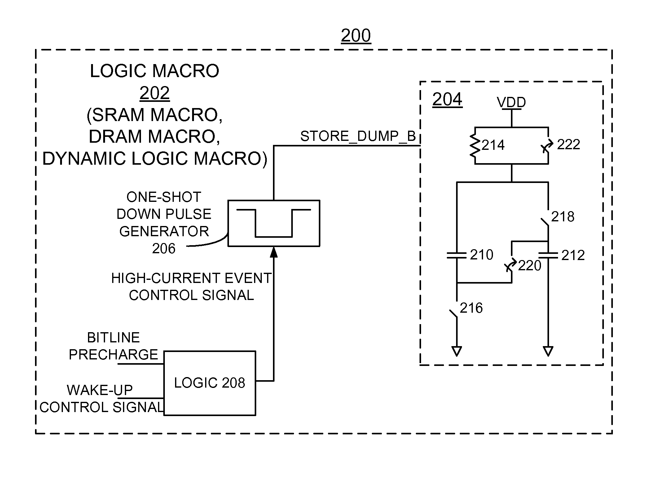
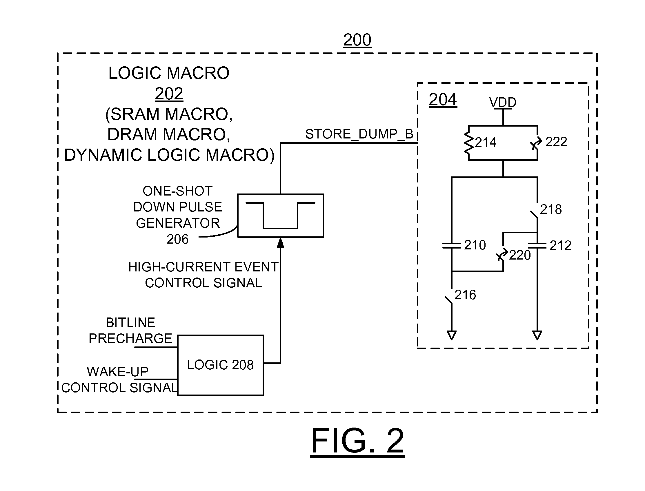
[0007]Principal aspects of the present invention are to provide a method and circuit for implementing smart switched decoupling capacitors to efficiently reduce power supply noise in a logic circuit with a high-current event control signal, such as a Static Random Access Memory (SRAM) circuit, Dynamic Random Access Memory (DRAM) circuit, or other dynamic logic circuit, and a design structure on which the subject circuit resides. Other important aspects of the present invention are to provide such method, circuitry and design structure substantially without negative effect and that overcome many of the disadvantages of prior art arrangements.
[0010]In accordance with features of the invention, the switched decoupling capacitor circuit reduces the power rail noise introduced by operation of the logic macro, including SRAM macros, without significantly increasing power consumption or design complexity of the logic macro or the SRAM macro.
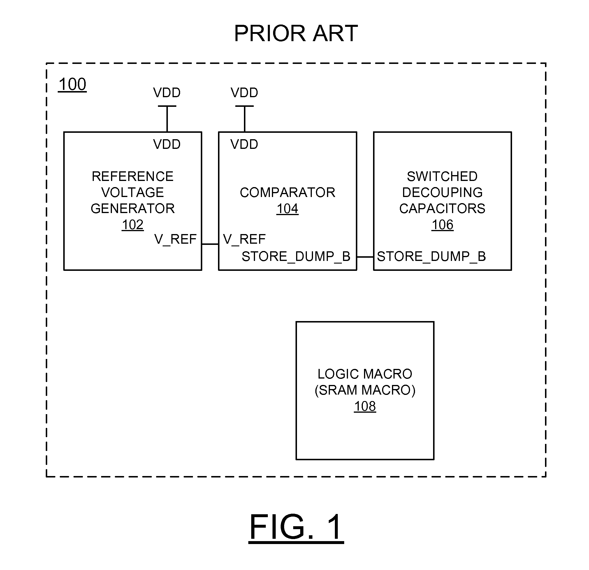
[0011]In accordance with features of the invention, the amount of decoupling capacitance required in nanometer scale technologies is reduced; as compared to prior art on-chip decoupling capacitor arrangements. The logic circuit with the switched decoupling circuit of the invention eliminates the need for high-overhead circuits to detect the power supply noise and control the switched decoupling capacitors. The logic circuit with the switched decoupling circuit of the invention eliminates the use of the reference voltage generator and the analog voltage comparator, that otherwise consume large amounts of power in prior art on-chip decoupling capacitor arrangements.

Problems solved by technology

As technology nodes progress, decoupling capacitors are consuming a progressively larger portion of chip area.
In general, current prior art switched decoupling capacitor schemes have significant drawbacks.

Method used


Image

  • Implementing smart switched decoupling capacitors to efficiently reduce power supply noise
  • Implementing smart switched decoupling capacitors to efficiently reduce power supply noise
  • Implementing smart switched decoupling capacitors to efficiently reduce power supply noise

Examples


Embodiment Construction

[0016]In the following detailed description of embodiments of the invention, reference is made to the accompanying drawings, which illustrate example embodiments by which the invention may be practiced. It is to be understood that other embodiments may be utilized and structural changes may be made without departing from the scope of the invention.

[0017]The terminology used herein is for the purpose of describing particular embodiments only and is not intended to be limiting of the invention. As used herein, the singular forms “a”, “an” and “the” are intended to include the plural forms as well, unless the context clearly indicates otherwise. It will be further understood that the terms “comprises” and / or “comprising,” when used in this specification, specify the presence of stated features, integers, steps, operations, elements, and / or components, but do not preclude the presence or addition of one or more other features, integers, steps, operations, elements, components, and / or gr...


PUM


Abstract

A method and circuit are provided for implementing smart switched decoupling capacitors to efficiently reduce power supply noise in a logic circuit, and a design structure on which the subject circuit resides. The logic circuit includes a logic macro, a high-current event control signal activating a logic function, and a switched decoupling capacitor circuit integrated within the logic macro. The switched decoupling capacitor circuit uses the high-current event control signal to control capacitor switching to discharge to a voltage supply rail responsive to activating the logic function, and to charge the capacitors.

Description

FIELD OF THE INVENTION[0001]The present invention relates generally to the data processing field, and more particularly, relates to a method and circuit for implementing smart switched decoupling capacitors to efficiently reduce power supply noise in a logic circuit with a high-current event control signal, such as a Static Random Access Memory (SRAM) circuit, Dynamic Random Access Memory (DRAM) circuit, or other dynamic logic circuit, and a design structure on which the subject circuit resides.DESCRIPTION OF THE RELATED ART[0002]As technology nodes progress, decoupling capacitors are consuming a progressively larger portion of chip area. Switched decoupling capacitors are becoming a popular method to limit the area consumed by decoupling capacitance and improve the effectiveness of the decoupling capacitance at reducing power supply droop.[0003]The basic principle of switched decoupling capacitors can be understood as follows. Two capacitors are initially connected in parallel stor...

Claims


Application Information

Patent Timeline
Patent Type & Authority Patents(United States)
IPC IPC(8): G11C5/14
CPCG11C7/02H03K19/00346
Inventor HEBIG, TRAVIS REYNOLDPAULSEN, DAVID PAUL
Owner IBM CORP
Why Eureka
Try Eureka