Load release pin for concrete shoring apparatus

a technology of concrete shoring and load release pin, which is applied in the direction of couplings, rod connections, manufacturing tools, etc., can solve the problems of high load on shore posts, and difficulty in turning threaded couplings under high load, so as to achieve the effect of easy movement or displacemen

Inactive Publication Date: 2007-11-15
WILIAN HLDG
View PDF1 Cites 15 Cited by
  • Summary
  • Abstract
  • Description
  • Claims
  • Application Information

AI Technical Summary

Benefits of technology

[0006] The preferred embodiment of the present invention consists of a load release pin that supports a pair of telescoping tubes of a shore post in a loaded, working position supporting concrete forming apparatus during the forming of concrete structures. Upon sufficient curing or setting of the concrete, the pin is easily moved or displaced to allow the tubes to telescopically collapse and so relieve the load on the shore post to allow it to be disassembled or moved.

Problems solved by technology

Because of the weight of the concrete poured on the form panels, the shore posts are under a high load.
Workers have difficulty relieving the load on the shore posts.
In many systems on the market, a threaded coupling is used to adjust the length of the shore post and turning the threaded coupling under high load is difficult.
A disadvantage of the existing pin systems is that the pin is made from cylindrical stock with notches milled in it to create the reduced thickness sections.
Another problem is that if the pin is mistakenly left in the load relieved, reduced thickness position when the shore post is used to support plastic concrete, the pin may not provide the specified strength or safety factor and could fail.

Method used


Image

  • Load release pin for concrete shoring apparatus
  • Load release pin for concrete shoring apparatus
  • Load release pin for concrete shoring apparatus

Examples


Embodiment Construction

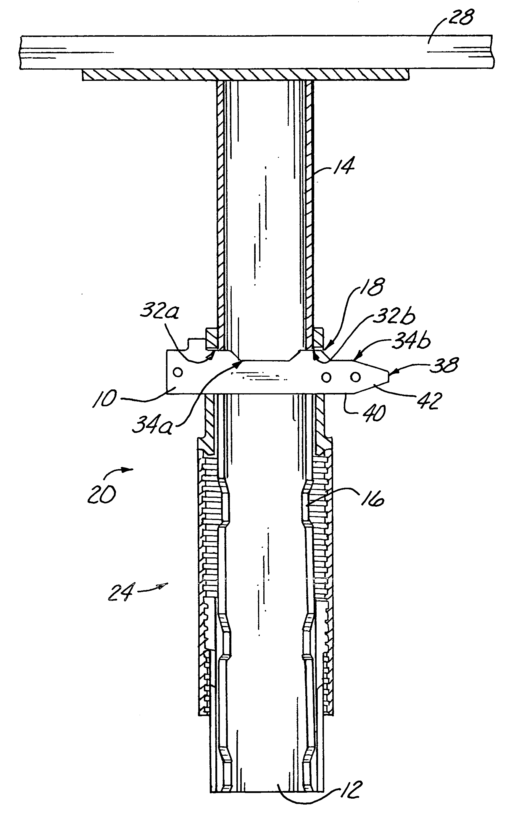
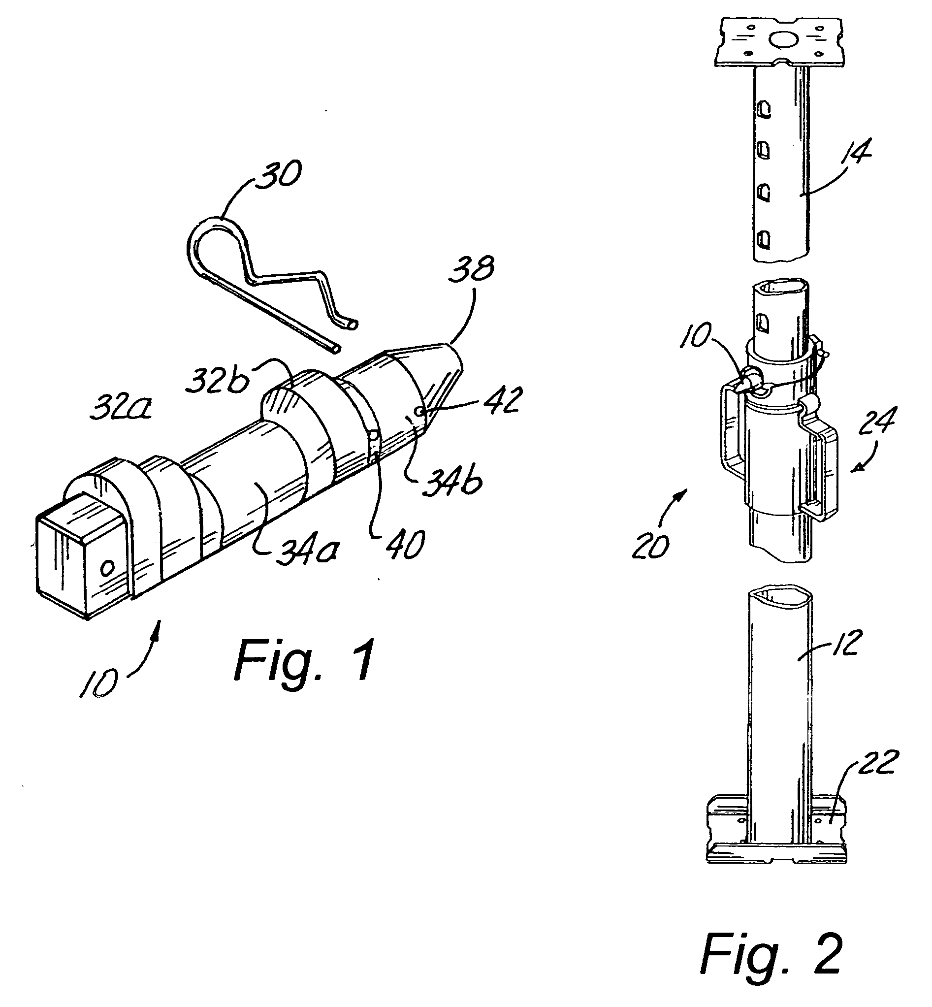
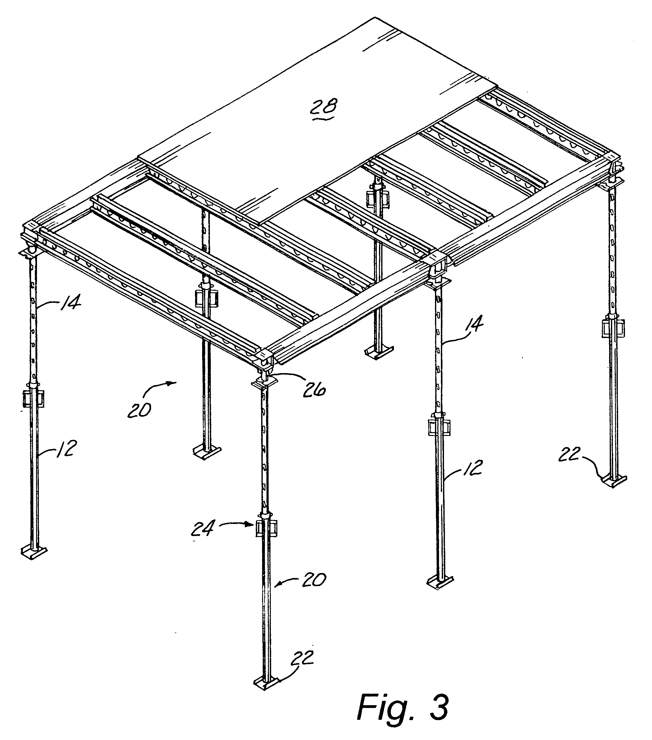
[0016] Illustrated in FIG. 1, generally at 10, is a load release pin representing a preferred embodiment of the present invention. The pin 10 is inserted into a pair of telescoping tubes, outer tube 12 and inner tube 14 (FIGS. 4 and 5). The body member of the pin 10 has a profile in transverse cross-section that is asymmetric. In a preferred embodiment, its transverse profile of the body member has a “tombstone” shape, that is an arcuate top profile, straight sides, and a flat bottom. Each of the outer tube 12 and inner tube 14 is provided with a pair of diametrically opposed openings 16 and 18, respectively, that are of a corresponding asymmetric profile as that of the pin 10, that is, an arcuate top profile, straight sides and a flat bottom, but slightly enlarged to permit passage of the pin 10. The asymmetric profile of the pin 10 and the corresponding openings 16 and 18 make it impossible for the pin 10 to be inserted into the tubes 12 and 14 in anything other than the desired o...


PUM


Abstract

A load release pin for concrete forming apparatus is disclosed. The pin supports the concrete forming apparatus and any plastic concrete during forming of a concrete structure. After the concrete has set sufficiently, the pin is displaced to release the load on the forming apparatus. The pin has an asymmetric shape that prevents it from being used in an incorrect orientation. In addition, the pin provides sufficient strength to safely support the forming apparatus and any plastic concrete even if it is mistakenly inserted in the displaced position.

Description

BACKGROUND OF THE INVENTION [0001] The invention relates generally to concrete form apparatus and, more specifically, to a pin that is used to support concrete shoring apparatus in a loaded, working position and which may be readily displaced to relieve the load on the shoring apparatus so that the shoring apparatus may be disassembled, moved, or the like. [0002] Concrete forming apparatus is in wide use in the construction of buildings, bridges, and other concrete structures. A common system for forming concrete structures uses a plurality of modular form components that are adapted to be assembled into a wide variety of configurations to conform to virtually any architectural requirement. Such forming apparatus components are typically made of metal so that they are strong enough to support the heavy weight of poured concrete and durable so that the components can be reused many times. [0003] A common application of concrete forming apparatus is in the formation of horizontal slab...

Claims


Application Information

Patent Timeline
Patent Type & Authority Applications(United States)
IPC IPC(8): F16B21/09
CPCE04G25/061F16B7/105F16B21/12E04G25/068Y10T403/58E04G25/06E04G11/38E04G11/48E04G25/063E04G25/066F16B2200/69
Inventor MCCRACKEN, ROBERT
Owner WILIAN HLDG
Why Eureka
Try Eureka