
Quadrature sub-harmonic frequency up-converter

a sub-harmonic frequency and up-converter technology, applied in the field ofradar and wireless communications systems, can solve the problems of complex circuits, need for all-in-one local oscillator, and high cost, and achieve the effect of reducing increasing the complexity of circuits, and increasing the cost of circuits

Inactive Publication Date: 2007-11-15
COBHAM DEFENSE ELECTRONICS SYST CORP
View PDF9 Cites 15 Cited by
  • Summary
  • Abstract
  • Description
  • Claims
  • Application Information

AI Technical Summary

Benefits of technology

[0015] The invention is a method and apparatus for frequency up-converting a first data signal centered at a first frequency to a second data signal containing the same data as the first data signal and centered at a second frequency higher than the first frequency involving generating first and second oscillator signals having a third frequency that is about ⅓ of the second frequency, the first oscillator signal being 90° out of phase with the second oscillator signal; receiving the first data signal; mixing the first data signal with the first oscillator signal to produce a first component of a third data signal centered at a fourth frequen

Problems solved by technology

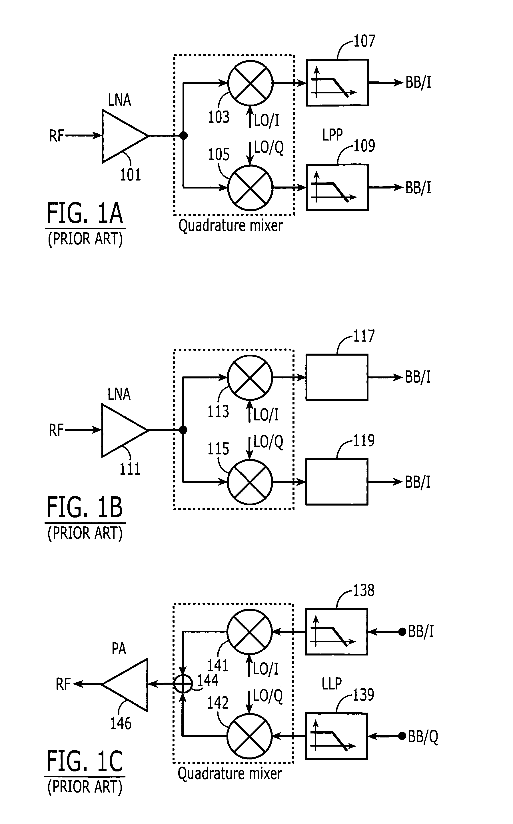
One of the disadvantages of the heterodyning technique is that it requires two local oscillators and their incumbent circuitry, expense, and complexity.
A significant disadvantage of direct conversion, however, is the need for a local oscillator that oscillates all the way up at the FRF frequency (or very close to it, in the case of a low-IF technique).
Generally, the higher the frequency at which a circuit must operate, the more complex, power-hungry, and expensive that circuit tends to be.
Accordingly, direct frequency up-conversion and down-conversion in connection with these signals would require very high frequency (and therefore very complex, very expensive, and very power-hungry) local oscillators and phase locked loops (PLLs).

Method used


Image

  • Quadrature sub-harmonic frequency up-converter
  • Quadrature sub-harmonic frequency up-converter
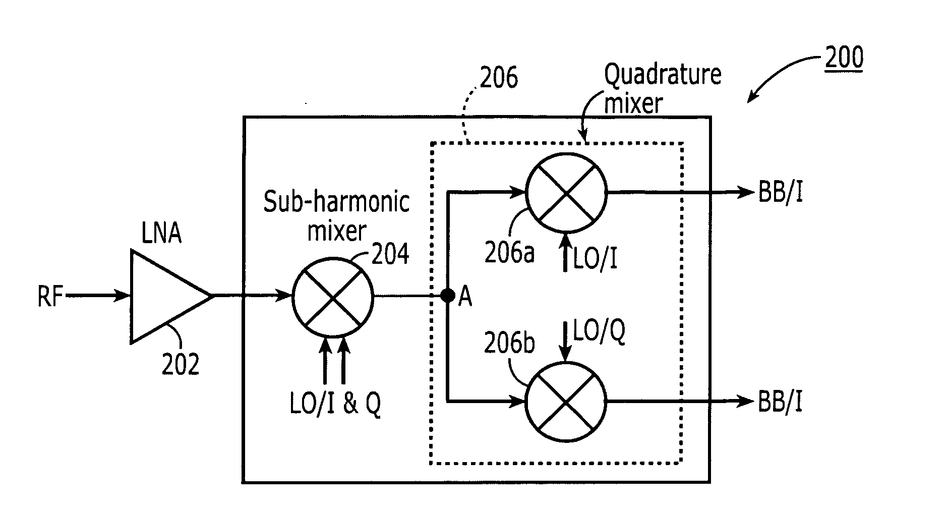
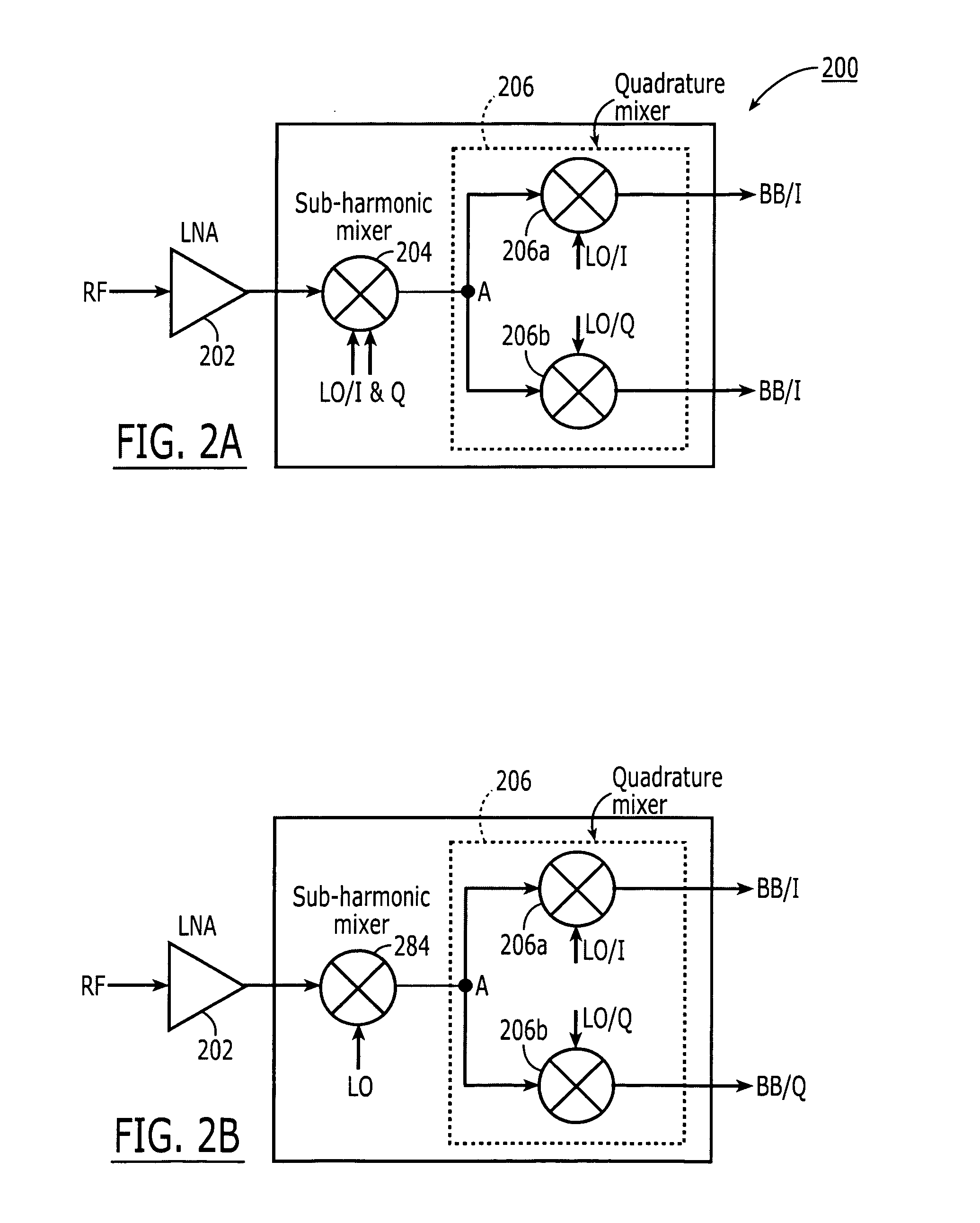
  • Quadrature sub-harmonic frequency up-converter

Examples


Embodiment Construction

[0027] The present invention pertains to a quadrature sub-harmonic frequency down-converters and up-converters that frequency convert between baseband and and RF in two stages having the advantages of requiring only a single local oscillator frequency much lower than the received RF signal frequency.

[0028] The invention uses the two quadrature components of a single local oscillator signal. Using a down-converter as an example, the first stage, the RF signal is mixed with both components of a local oscillator signal (LO) at or about one third the RF frequency in a sub-harmonic mixer using multi-phase LO signals, in this case, two signals in quadrature, to produce an intermediate frequency output signal (IF) having a frequency of twice the local oscillator frequency minus the RF frequency. i.e., 2FLO−FRF=⅓FRF=FIF. In a second stage, that IF signal is split into two and supplied to a quadrature mixer that mixes the IF signal with the I component of the same local oscillator signal an...


PUM


Abstract

A method and apparatus for frequency up-converting a baseband signal to radio frequency (RF) in two steps using the two quadrature components of a single local oscillator signal. In a first stage, the baseband signal is split into two parts in quadrature with each other and supplied to a quadrature mixer that mixes the one component of the baseband signal with the I component of a local oscillator signal at frequency FLO and separately mixes the other baseband component with the Q component of the same local oscillator to produce an intermediate frequency signal centered at the local oscillator frequency and comprising two components, namely, an I component and a Q component. In the second stage, the intermediate frequency signal is mixed with both components of the same local oscillator signal in a sub-harmonic mixer-to produce a radio frequency output signal having a frequency component at three times the local oscillator frequency minus the baseband frequency.

Description

FIELD OF THE INVENTION [0001] The invention pertains to radar and wireless communications systems, such as cellular telephone communications systems and television and radio communications systems. BACKGROUND OF THE INVENTION [0002] Generally, in any type of wireless communication system, baseband voice or data signals are carried on a radio frequency (RF) carrier frequency. Thus, circuitry must be provided in a transmitter that places the baseband signal on the RF carrier signal. This process is commonly termed frequency up-conversion and the circuitry that performs this process is commonly called a frequency up-converter. Likewise, in the receiver, the baseband signal must be extracted from the incoming RF receive signal picked up by the receive antenna. This process is commonly termed frequency down-conversion and the circuitry that performs this process is commonly called a frequency down-converter. [0003] There are several techniques in common use for performing frequency up-co...

Claims


Application Information

Patent Timeline
IPC IPC(8): H04B1/04H04B1/26H01Q11/12
CPCH03D7/1441H03D7/1433H03D7/165H03D7/1475H03D7/1458
Inventor CARREZ, FREDERIC
Owner COBHAM DEFENSE ELECTRONICS SYST CORP
Learn More