Method of making an optical fiber

a technology of optical waveguide fibers and fibers, which is applied in the field of making optical waveguide fibers, can solve the problems of limiting the use of single polarization fibers for high power applications, difficult to achieve large mode field diameters, and difficult to obtain structures with conventional manufacturing methods

Inactive Publication Date: 2007-11-22
CORNING INC
View PDF10 Cites 39 Cited by
  • Summary
  • Abstract
  • Description
  • Claims
  • Application Information

AI Technical Summary

Problems solved by technology

These structures are more difficult to obtain with the conventional manufacturing methods.
Single polarization fibers with a plurality of air-holes are known, however such fibers have a high relative refractive index core delta which makes it difficult to achieve large mode field diameter.
Therefore, to maintaining single mode operation, the fiber core must be small, which limits the use of single polarization fibers for high power application.

Method used


Image

  • Method of making an optical fiber
  • Method of making an optical fiber
  • Method of making an optical fiber

Examples


example 1

[0099]FIG. 19A shows the cross-section of a highly dispersive, non-linear optical fiber made with the current invention having 6 holes adjacent to the high Ge-doped core in the single-clad fiber. Using this fiber structure, generally average refractive index delta from −30% to 0% percent can be made depending on the number of holes in the cladding. The holes in the inner cladding make the average index lower than the pure silica, creating an effective depressed cladding structure. The average index value depends on the how many air holes or the percentage of air volume in the inner-cladding layer. The low depressed cladding delta enables making very small effective area fibers. On the other hand, the fibers are much easier to make by the method described in this invention than those used in the conventional photonic crystal fiber making. The structure allows us to make an effective area as small as 5-10 μm2, and dispersion between 0-80 ps / nm.km at 1550 nm for nonlinear fiber-optic a...

example 2

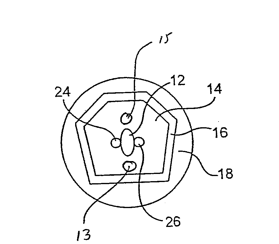
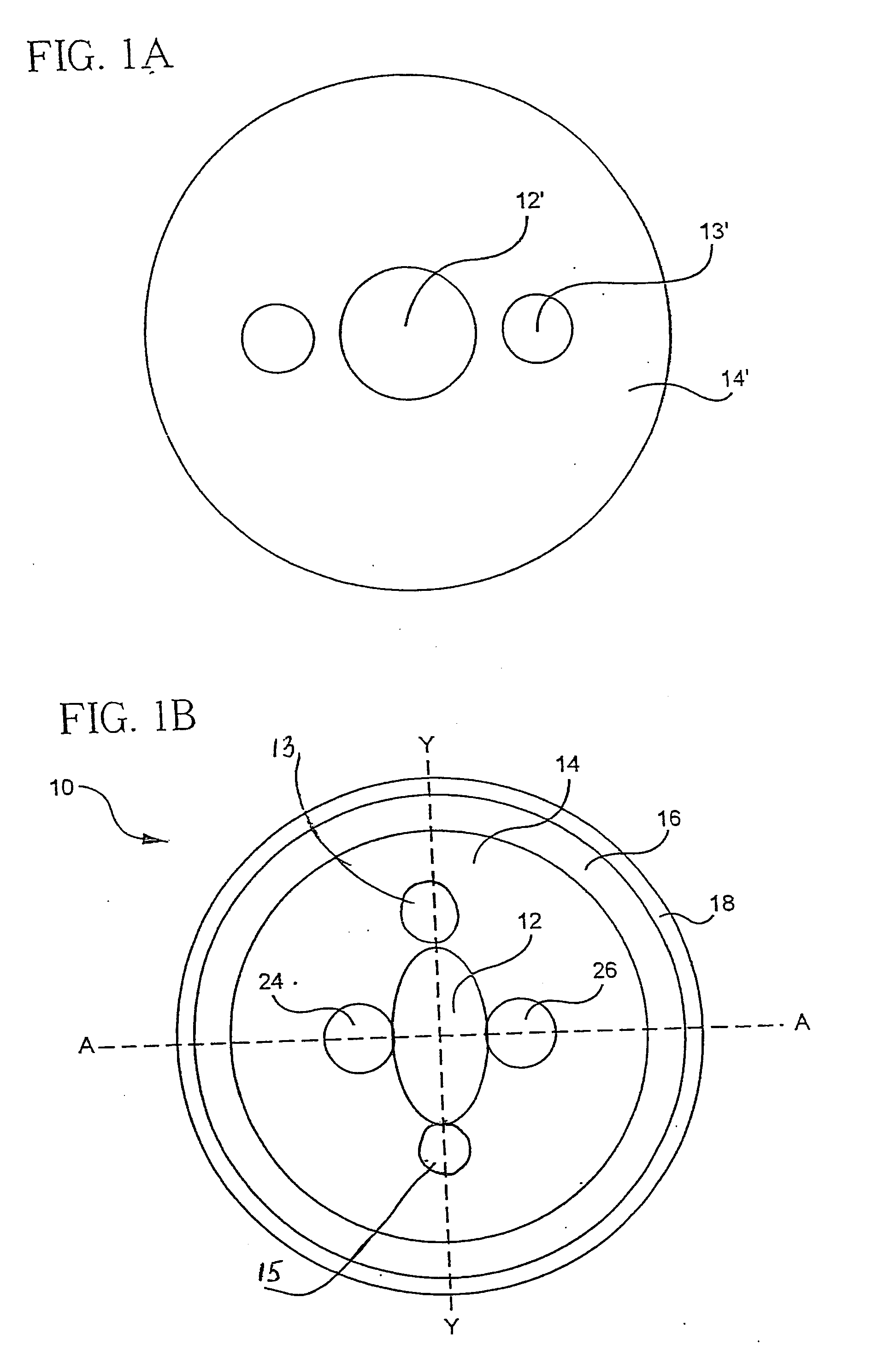
[0100]FIG. 20 shows the process flow of the invented method for making dual air-hole double-clad fiber in Suppression of stimulated Raman gain in high-power fiber lasers when employing such fiber as the gain media. Dual-hole-assisted fiber is a typical micro-structured fiber including of a glass core and a cladding having two air-holes running along the fiber length. These holes 24, 26 are adjacent to the core 12 and are symmetrically placed relative to the core center along a common axis comprising the core and holes′ centers. An important property of dual-hole-assisted fiber is that of having a fundamental-transverse mode cut-off wavelength. Through proper design, this cut-off wavelength can be polarization resolved, thus providing the means to achieve single-polarization propagation. The spectral range between the cut-off wavelengths of each of the two orthogonal polarization modes defines the single-polarization bandwidth of this fiber. By carefully overlapping the single-polari...


PUM

PropertyMeasurementUnit
microstructuresaaaaaaaaaa
microstructuredaaaaaaaaaa
index of refractionaaaaaaaaaa

Abstract

According to one embodiment a method of making optical fibers comprises: (i) manufacturing a core cane; (ii) situating a plurality of microstructures selected from rods, air filled tubes and glass filed tubes and placing said microstructures adjacent to the core cane, said microstructures forming no more than 3 layers; (iii) placing the core cane with said adjacent microstructures inside a holding clad tube; and (iv) placing interstitial cladding rods inside the holding (clad) tube, thereby forming an assembly comprising a tube containing a core cane, a plurality of microstructures and interstitial cladding rods. The assembly is then drawn into a microstructured cane and an optical fiber is drawn from the microstructured cane. According to several embodiments, the method of making an optical fiber includes providing at least one air hole and at least one stress rod adjacent to the core.

Description

BACKGROUND OF THE INVENTION[0001]1. Field of the Invention[0002]The present invention relates generally to a method of making optical waveguide fibers, and more particularly to a method of making optical fibers having a plurality of rods and / or holes.[0003]2. Technical BackgroundBACKGROUND OF THE INVENTION[0004]1. Field of the Invention[0005]The present invention relates generally to polarization maintaining and single polarization optical fibers that include a plurality of rods and / or a plurality of air holes in the cladding area.[0006]2. Technical Background[0007]Optical fiber has become a favorite medium for telecommunications due to its high capacity and immunity to electrical noise. Polarization maintaining (PM) fibers and single polarization (SP) fibers have been widely used to produce linear polarized output in optical systems. These fibers are useful for ultra-high speed transmission systems and are also utilized as couplers fiber for use with, and connection to, optical com...

Claims


Application Information

Patent Timeline
Patent Type & Authority Applications(United States)
IPC IPC(8): C03B37/022C03B37/15C03B37/027
CPCC03B37/01211C03B37/01217C03B2201/10C03B2201/14C03B2203/31C03B2201/34C03B2201/36C03B2203/12C03B2203/14C03B2201/31
Inventor GALLAGHER, MICHAEL THOMASLI, MING-JUNMCCARTHY, JOSEPH EDWARDWANG, JIZENTENO, LUIS ALBERTO
Owner CORNING INC
Why Eureka
Try Eureka