Saw blade mounting structure of a scroll saw

a scroll saw and mounting structure technology, applied in fret saws, metal sawing devices, manufacturing tools, etc., can solve problems such as complicated mounting procedures, and achieve the effect of easy replacement of saw blades

Inactive Publication Date: 2007-11-22
REXON IND CORP LTD
View PDF37 Cites 6 Cited by
  • Summary
  • Abstract
  • Description
  • Claims
  • Application Information

AI Technical Summary

Benefits of technology

[0008]Because the second rod member is eccentrically connected to one end of the first rod member remote from the operating member, the first rod member is turned aside from the central axis of the second rod member to move the clamping block toward the stop flange of the mounting block to clamp the saw blade when the operating member is rotated. When replacing the saw blade, the operating member is rotated in the opposite direction to move the clamping block apart from the stop flange, thereby releasing the saw blade. The use of the clamps allows for easy replacement of the saw blade without tools. Further, the large clamping area between the stop flange and the clamping face ensures a tight connection of the saw blade to the mounting block.

Problems solved by technology

This mounting procedure is complicated.

Method used


Image

  • Saw blade mounting structure of a scroll saw
  • Saw blade mounting structure of a scroll saw
  • Saw blade mounting structure of a scroll saw

Examples


Embodiment Construction

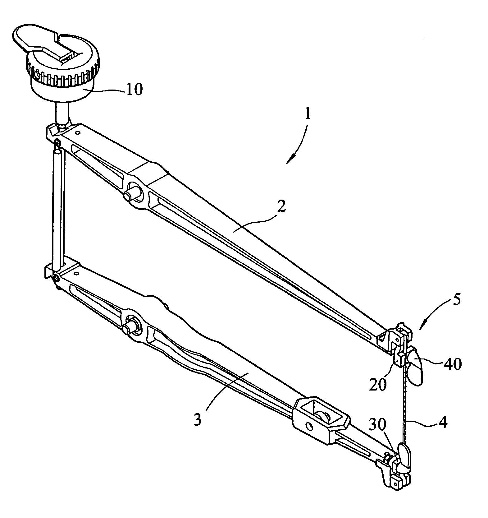
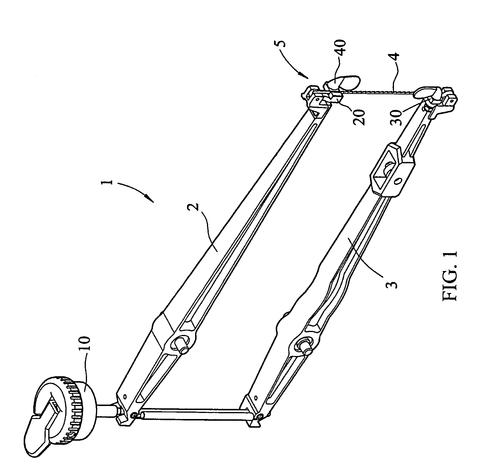
[0016]Referring to FIGS. 1 and 2, a scroll saw 1 is shown comprising an upper arm 2 and a lower arm 3 arranged horizontally in a parallel manner, an adjustment device 10 adapted to adjust the gap between the upper arm 2 and the lower arm 3, a saw blade 4, and two clamps 5 respectively fastened to one end of the upper arm 2 and the corresponding end of the lower arm 3 to hold the saw blade 4 vertically between the upper arm 2 and the lower arm 3. The scroll saw 1 further comprises a worktable (not shown). The saw blade 4 is inserted through an opening (not shown) on the worktable and is moved vertically with the upper arm 2 and the lower arm 3 to cut a workpiece that is placed on the worktable and moved toward the saw blade 4.

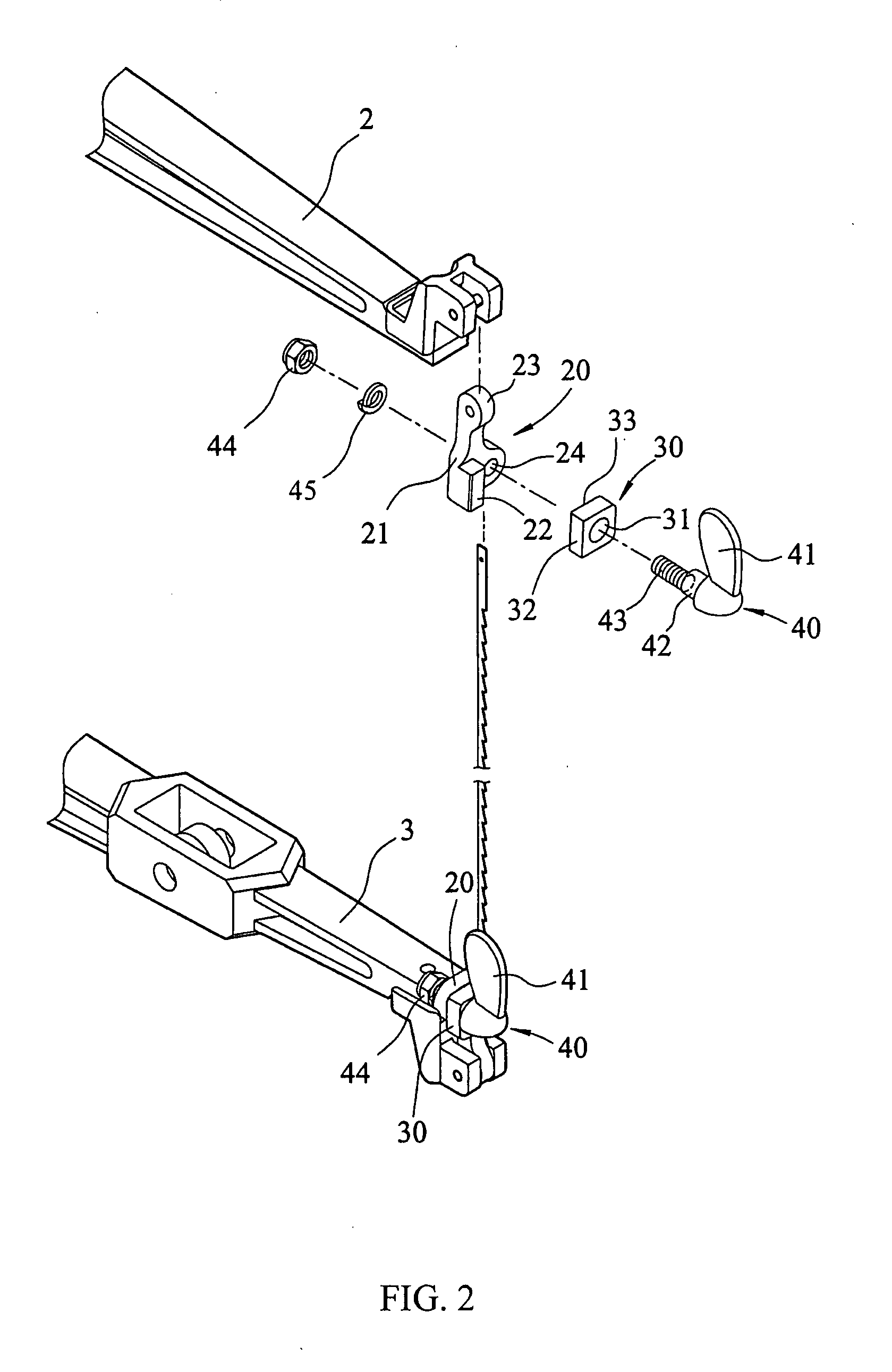
[0017]The aforesaid clamps 5 each are comprised of a mounting block 20, a clamping block 30, and a lock 40.

[0018]The mounting block 20 comprises a base 21, a stop flange 22 perpendicularly extending from one side of the base 21, a lug 23 disposed at the top side...


PUM

PropertyMeasurementUnit
rotationaaaaaaaaaa
dimensionaaaaaaaaaa
stretching forceaaaaaaaaaa

Abstract

A saw blade mounting structure formed of two saw blade clamps and used in a scroll saw to hold a saw blade between two suspension arms in which each saw blade clamp comprises a mounting block pivotally connected to one suspension arm and provided with a through hole and a stop flange, a clamping block with a through hole, an operating member, a first rod member fixedly connected to the operating member and inserted through the through hole of the clamping block, a second rod member eccentrically extending from one end of the first rod member and inserted through the through hole of the mounting block and screwed into a check nut for enabling the first rod member to move the clamping block relative to the stop flange of the mounting block so as to lock/release the saw blade upon forward/backward rotation of the operating member.

Description

BACKGROUND OF THE INVENTION[0001]1. Field of the Invention[0002]The present invention relates to a scroll saw and more specifically, to a saw blade mounting structure for a scroll saw.[0003]2. Description of the Related Art[0004]A scroll saw is a fine-toothed saw with a narrow blade, used to cut curved outlines. A scroll saw generally comprises an upper arm, a lower arm, and a saw blade fastener provided at one end of each of the upper arm and the lower arm to hold a saw blade across a worktable on which the workpiece is placed and moved toward the saw blade for cutting by the saw blade.[0005]FIGS. 4 and 5 show a saw blade mounting structure for a scroll saw according to the prior art. According to this design, the saw blade mounting structure comprises two saw blade fasteners respectively provided at the distal end of each of an upper arm 60 and a lower arm 61 to hold a saw blade 65. Each saw blade fastener comprises a U-bar 62, which is fixedly fastened to the distal end of the ar...

Claims


Application Information

Patent Timeline
Patent Type & Authority Applications(United States)
IPC IPC(8): B27B19/10
CPCB23D51/14Y10T83/705Y10T83/9481
Inventor CHEN, JUNG-HUO
Owner REXON IND CORP LTD
Why Eureka
Try Eureka